Cadence公司的数字IC设计工具:综合工具(Genus)——(3)
目录
前言
一、Genus Physical Guide
1、介绍
2、The simple PLE flow
2.1 Reading the LEF Libraries
2.2 Loading the Parasitic Information
2.3 检查LEF和寄生文件之间的一致性。
2.4 checking the physical layout estimation information
2.5 setting the appropriate synthesis mode
2.6 reading the floorplan
2.7 synthesis
2.8 Analyzing the results
2.9 exporting files for place and route
二、Low Power
1、介绍
1.1 挑战
1.2 Traditional Low Power Synthesis Features
1.2.1 Power analysis
1.2.2 Power Optimization
1.3 通过(Common Power Format)支持高级Power管理技术
1.4 required files for low power synthsis
2、power analysis concepts
2.1 Power Dissipation Components
2.1.1 leakage power dissipation (cell leakage power)
2.1.2 net power dissipation (net power)
2.1.3 internal power dissipation (cell internal power)
2.2 power calculation
3、providing switching activity information
3.1 introduction
3.2 sources of switching activity information
3.3 using attributes to apply switching activities
3.3.1 using default switching activities
3.3.2 specifying net switching activities
3.3.3 propagating net switching activities
3.4 reading switching activity information from a TCF file
3.4.1 reading a TCF file with modified clock frequency
3.4.2 Reading multiple CPF files with different weights
3.5 reading switching activity information from a SAIF file
3.6 reading switching activity information from a VCD file
4、power analysis
4.1 RTL power analysis
4.2 reporting clock tree power
4.3 reporting on all power components
4.4 reporting power on leaf instances
4.5 reporting power consumption per used cell types
5、Clock Gating
5.1 introduction
5.2 enabling clock gating
5.3 inserting clock gating
6、Leakage Power Optimization
6.1 介绍
6.2 prerequisites
6.3 Reading Multiple Vth Libraries
6.4 Using Dedicated Libraries for Power Optimization
6.5 enabling leakage power optimization
6.6 Controlling power optimization
6.6.1 using a weight factor to balance leakage and dynamic power optimization
6.6.2 controlling tradeoff between leakage power and area, delay and runtime
7、Dynamic Power Optimization
7.1 introduction
7.2 enabling dynamic power optimization
7.3 Controlling power optimization
三、Using CPF for Multiple Supply Voltage Designs
1、 overview
1.1 power domain
1.2 power mode
1.3 library set
1.4 level shifters
2、CPF文件
2.1 指定libraries
2.2 指定要使用的level shifter cells
2.3 声明CPF文件中描述的设计
2.4 指定power domains
2.5 指定设计中使用的工作电压
2.6 将nominal condition与power domain相关联
2.7 指定要用于nominal condition的libraries
2.8 指定创建level shifter logic的rules
2.9 指定power约束 (可选)
2.10 指定timing约束 (可选)
2.11 指定activity information (可选)
2.12 使用实现信息更新rules
2.13 指定全局的接电和接地nets
2.14 指定全局连接
2.15 指定接电和接地路由的附加信息
3、flow steps
3.1 read the target libraries
3.2 read the power intent
3.3 apply the power intent
3.4 check the power intent
3.5 commit the power intent
3.6 verify added power logic
3.7 set timing, design, and power constraints
四、Using CPF for Design Using Power Shutoff Methodology
1、overview
1.1 power domain
1.2 power mode
1.3 isolation cells
1.4 state retention cells
1.5 power switch cells
1.6 special control signals
1.7 primary and secondary domain
2、flow steps
2.1 specifying the libraries
2.2 specifying the isolation cells to use
2.3 specifying the always-on cells
2.4 specifying the state retention cells to be used
2.5 specifying the power switch cells to be used
2.6 declaring the design described in the CPF file
2.7 specifying the power domains
2.8 specifying the operating voltage used in the design
2.9 specifying the static behavior in each power mode
2.10 specigying the libraries to use for a condition
2.11 specifying the rules to create isolation logic
2.12 specifying the rules to create state retention logic
2.13 指定power约束 (可选)
2.14 指定timing约束 (可选)
2.15 指定activity information (可选)
2.16 使用实现信息更新rules
参考
前言
前两篇文章介绍了Genus如何进行logic synthesis,具体见:Cadence公司的数字IC设计工具:综合工具(Genus)——(1)_qq_42922513的博客-CSDN博客
https://blog.csdn.net/qq_42922513/article/details/131410678?spm=1001.2014.3001.5502
Cadence公司的数字IC设计工具:综合工具(Genus)——(2)_qq_42922513的博客-CSDN博客
本文介绍如何进行physical synthesis,以及低功耗分析和设计。
本文内容适用于genus -legacy_ui用户接口。
一、Genus Physical Guide
综合优化的对象是 timing path,而 timing path delay = net delay + cell delay,90nm工艺之前由cell delay 主导,而进入65nm后,net delay的占比日渐增加,进入40nm之后,net delay几乎跟cell delay平分秋色,所以从40nm开始,physical aware synthesis 开始被使用,因为physical aware synthesis在优化过程中可以看到更精确的net delay。
1、介绍
传统的综合工具使用供应商提供的基于扇出的线负载模型(wire-load models),它不能提供准确的线延迟信息,特别是对于很大一部分延迟是由线造成的设计。因此,可以看到逻辑和物理设计之间在性能、面积和功耗方面存在相对较大的差异。
物理布局估计(Physical layout estimation (PLE) )使用物理信息来根据RTL的当前状态和约束对放置效果进行建模,并提供传统综合方法无法提供的分析和优化级别。此外,使用物理信息提供了一定程度的下游(down-stram)可预测性,优于使用供应商提供的线路负载模型。可预测性使用户能够更好地衡量设计在放置(place)和路由(route)后的执行情况,并有助于减少前端到后端交接迭代。最终,在综合中使用物理信息使用户有机会在更短的时间内开发出比传统合成更小、更快的设计。
Genus提供了三种与物理相关的流程。它们在预测导线长度方面提供了越来越高的准确性。分别为:(1)The simple PLE flow;(2)The Genus-Spatial flow;(3)The Genus-Physical flow
2、The simple PLE flow
2.1 Reading the LEF Libraries
LEF文件是包含物理库信息的ASCLL文件,例如层、通道、放置(placement)站点类型、路由设计规则、过程信息以及标准单元和宏单元定义。技术信息和单元定义通常在单独的LEF文件中提供,以便于管理。
指定所有LEF文件,包括技术库(technology library,tec.lef)和单元库(cell libraries,cell.lef)。先指定tec.lef文件。
set_attribute lef_library {tech.lef cell.lef}2.2 Loading the Parasitic Information
电容表文件(Capacitance tables' files )或QRC技术文件(QRC technology files)包含与LEF文件相同类型的寄生信息,但这些文件中的电阻和电容信息具有更细的粒度。对于28nm以下的技术,Innovus系统需要QRC技术文件而不是电容表文件。
LEF中的电容来自铸造厂(foundry),并由其认为合适的任何工艺产生。电容表或QRC技术文件中的电容信息来自驱动签名提取以及Cadence工具中使用的各种其他提取器的相同过程定义文件。过程定义文件定义层的厚度、组成和间距。
set_attribute cap_table_file  /
set_attribute qrc_tech_file  /
如果同时指定电容表文件和QRC技术文件,则QRC技术文件优先。建议同时指定LEF和寄生文件。但是,如果寄生文件不可用,则只需指定LEF文件。
2.3 检查LEF和寄生文件之间的一致性。
在加载LEF和寄生文件之后,Genus将在这两个文件之间执行一致性检查。这是自动发生的。
2.4 checking the physical layout estimation information
report ple2.5 setting the appropriate synthesis mode
Genus有两种综合模式:wireload和ple。模式由interconnect_mode属性定义。当读入LEF库时,interconnect_mode属性自动设置为ple。
2.6 reading the floorplan
当使用PLE时,应该以floorplan的形式提供物理约束。在Genus中,通过DEF文件(.def)提供floorplan信息。
read_def 2.7 synthesis
syn_generic -physical
syn_map -physical
syn_opt -physical -incremental
2.8 Analyzing the results
2.9 exporting files for place and route
write_design -innovus二、Low Power
涉及到的工艺库相关内容可参考:数字IC设计工艺库简介_qq_42922513的博客-CSDN博客![]() https://blog.csdn.net/qq_42922513/article/details/131554681
https://blog.csdn.net/qq_42922513/article/details/131554681
1、介绍
1.1 挑战
随着个人计算设备、消费电子产品和无线通信系统的显著成功和发展,人们迫切需要高速计算和复杂的功能。然而,功耗也成为一个关键的设计问题。由于芯片尺寸的缩小,单位面积的密度正在增加,因此高性能处理器(例如具有500-3000 MHz时钟的处理器)的封装和冷却策略的成本也在增加。
这些问题将焦点从设计性能和面积问题转移到对低功耗的需求和对功耗的考虑。随着今天的技术缩小到90纳米及以下,泄漏功率在功耗中的重要性也在增加。
1.2 Traditional Low Power Synthesis Features
当RTL网表准备好进行综合时,低功率综合(LP)将作为正常综合过程的一部分执行。
1.2.1 Power analysis
1.2.2 Power Optimization
power优化的主要特点是:
(1)Clock Gating
低功耗引擎探索设计,以确定在哪些地方可以通过为寄存器组插入时钟门控逻辑来节省潜在的功耗。为了减少不必要的时钟切换,Genus-LP engine为一组由相同同步信号使能的寄存器插入时钟门控逻辑。
(2)Leakage Power Optimization
(3)Dynamic Power Optimization
1.3 通过(Common Power Format)支持高级Power管理技术
Common Power Format(CPF)通过捕获设计人员对advanced power management techniques的意图,解决了设计自动化工具流中的当前限制。CPF以单一文件格式捕获所有与设计和技术相关的power constraints,用于从RTL到GDSII的整个设计流程,包括verification、validation、synthesis、test、physical implementation和signoff analysis。advanced power management techniques包括:
(1)Using Multiple Supply Voltages (MSV) in a design
这是降低设计动态功耗的最有效方法之一。动态功耗是电源电压的二次函数。对时序关键路径上的块使用高电压供电,而对非关键时序路径上的块使用低电压供电,可以在满足时序要求的同时显著节省动态功率。
(2)Using the Power Shut Off (PSO) methodology
使用这种方法,设计的某些部分可以根据需要打开和关闭,以节省泄漏和动态功率。
(3)Using dynamic voltage frequency scaling (DVFS)
当不需要峰值性能时,DVFS通过降低电压和频率来降低芯片中的功率。使用DVFS的设计可以看作是MSV设计在多种设计模式下运行的特殊情况。
1.4 required files for low power synthsis
(1)library
(2)RTL
(3)CPF file if use advanced power management techniques
(4)constraints file
(5)TCF or SAIF file
精确的功率分析或功率优化设计需要设计中每个pin(或net)的switching activity information。TCF是描述设计中switching activity information的Cadence标准。目前,TCF文件可以通过
a、write_tcf命令由RTL Compiler或Genus生成。
b、模拟设计生成。即对Cadence NC-Verilog模拟器使用dumptcf命令。可参考:Cadence公司的数字IC设计工具:仿真工具(INCISIVE)——(2)_qq_42922513的博客-CSDN博客![]() https://blog.csdn.net/qq_42922513/article/details/132078071?csdn_share_tail=%7B%22type%22%3A%22blog%22%2C%22rType%22%3A%22article%22%2C%22rId%22%3A%22132078071%22%2C%22source%22%3A%22qq_42922513%22%7D
https://blog.csdn.net/qq_42922513/article/details/132078071?csdn_share_tail=%7B%22type%22%3A%22blog%22%2C%22rType%22%3A%22article%22%2C%22rId%22%3A%22132078071%22%2C%22source%22%3A%22qq_42922513%22%7D
2、power analysis concepts
2.1 Power Dissipation Components
2.1.1 leakage power dissipation (cell leakage power)
静态功耗是由于漏电流引起的,在CMOS 门中,漏电流主要来自4个源头:
(1)亚阈值漏电流(Sub-threshold Leakage):阈值电压越高,漏电功耗就越低。
(2)栅极漏电流(Gate Leakage):在以往的技术节点中,漏电电流一直以亚阈值漏电为主。但是从90nm开始,门极漏电几乎是亚阈值漏电的1/3。在某些情况下,在65nm工艺下,它可以等于亚阈值泄漏。
(3)栅极感应漏电流:占比比较小,所以一般不做分析。
(4)反向偏置结泄漏:占比比较小,所以一般不做分析。
2.1.2 net power dissipation (net power)
翻转功耗(Switching power):是一个门电路对输出电容进行充电和放电需要的功耗。简单的说就是一个门电路输出从0变到1和从1变到0所需要消耗的功耗。和电压,翻转率,负载电容有关。
2.1.3 internal power dissipation (cell internal power)
短路功耗:主要原因是由于短路造成的。因为在输入信号进行翻转时,信号的翻转不可能瞬时完成,因此PMOS和NMOS不可能总是一个截止另外一个导通,总有那么一段时间是使PMOS和NMOS同时导通,那么从电源VDD到地VSS之间就有了通路,就形成了短路电流。
2.2 power calculation
3、providing switching activity information
3.1 introduction
Genus-LP引擎使用probability和toggle rate数据来估计power。The probability and toggle rate data也被称为net switching activities。当工具执行power分析时,net switching activities不能改变。
3.2 sources of switching activity information
Genus-LP引擎使用以下顺序来确定lp_asserted_probability和lp_asserted_toggle_rate net属性的值。
(1)如果提供Toggle Count Format (TCF)文件、Switching Activity Interchange Format (SAIF)文件或Value Change Dump (VCD)文件,则Genus-LP引擎将从该文件读取net switching activities,并用这些值填充lp_asserted_probability和lp_asserted_toggle_rate net属性。
(2)如果希望手动断言switching activity information,可以使用以下命令设置net switching activities:
#Specifies the probability value of a signal on this subport being high for power estimation.  You can specify any value between 0 and 1.
set_attribute lp_asserted_probability float /designs/design/*/nets/net#Specifies the toggle rate (toggle count per toggle rate unit) of this net for the purpose of power estimation.  you can specify any positive value.
set_attribute lp_asserted_toggle_rate float /designs/design/*/nets/net
(3)对于时钟nets,除非用户从an activity file中断言了时钟引脚,否则Genus-LP引擎从时序约束中的时钟定义派生出net switching activities。对于功率分析,将使用这个用户断言的值来代替时钟定义约束。
(4)对于没有用户断言的交换活动的节点,generic - lp引擎可以:Use default switching activities(见下面3.3.1);或:Propagate switching activities to those nets that have no switching information asserted(见下面3.3.3)。
3.3 using attributes to apply switching activities
3.3.1 using default switching activities
如果想要快速的功率分析,可以选择应用默认的switching activities。工具默认signal probability为0.5,工具默认toggle rate为0.02,默认toggle rate的单位为每纳秒。
(1)要提供自定义的默认值,设置以下属性
set_attribute lp_default_probability float {design | hierarchical_instance}
set_attribute lp_default_toggle_rate float {design | hierarchical_instance}
(2)要考虑设计中时钟的影响,可以通过设置以下属性来关联缩放因子
set_attribute lp_default_toggle_percentage value {design | clock}如果在一个clock上设置,则该属性指定与该时钟一起使用的乘法因子,以修改受该时钟影响的任何活动传播起点的default toggle rate。活动传播起点的切换速率可通过将此缩放因子与相关时钟的切换速率相乘来导出。如果有多个时钟与指定的数据引脚相关,则使用最快的时钟。如果在design上设置此属性,则对所有时钟使用相同的缩放因子。
(3)如果要使用默认的probability and toggle rate values进行功率分析,将以下root属性设置为low
set_attribute lp_power_analysis_effort low /
#medium:propagates the switching activities in the design (default)
#high:propagates the switching activities in the design with higher accuracy
3.3.2 specifying net switching activities
要设置(覆盖)当前的net switching activities,使用以下命令:
set_attribute lp_asserted_probability float /designs/design/*/nets/net
set_attribute lp_asserted_toggle_rate float /designs/design/*/nets/net
3.3.3 propagating net switching activities
如果某些节点没有用户断言的switching activities,则Genus-LP引擎可以自动从包含断言值的fanin锥中的节点传播switching activities。如果fanin锥中的任何逻辑节点都不包含断言的值,则Genus-LP引擎将追溯到活动传播起点并传播默认的switching activities。
为了控制用于传播switching activities的effort,可以设置lp_power_analysis_effort根属性,如下所示:
#控制是否在设计中传播switching activities。默认为medium
set_attribute lp_power_analysis_effort {medium | low | high} /
low:不传播交换活动,而是使用默认设置。
mediu:在设计中传播切换活动。
high:在设计中以更高的精度传播开关活动。
3.4 reading switching activity information from a TCF file
Cadence的TCF文件包括the toggle count information和the probability of a net or pin to be in the logic 1 state。
#This command overwtites any existing information on the pins and nets
read_tcf [-scale scale_factor] file#update the toggle count information and probability information of the pins and nets, and the simulation period.
read_tcf [-scale scale_factor] [-weight weight_factor] -update file
3.4.1 reading a TCF file with modified clock frequency
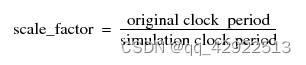
read_tcf -scale scale_factor file3.4.2 Reading multiple CPF files with different weights
you can specify any non-negative value for the weight. The default weight is 1.0. To give equal weight to old and new values of probability and toggle count, set the weight to 1.0.
read_tcf -update -scale scale_factor -weight weight_factor file 3.5 reading switching activity information from a SAIF file
SAIF文件提供了有关the switching behavior of nets and ports的详细信息,从而可以更准确地估计功率。Genus使用read_saif命令从SAIF文件中读取switching activity information,并在内部将其转换为TCF以进行功率估计。
read_saif file3.6 reading switching activity information from a VCD file
read_vcd vcd_file#If no options are specified, static power analysis is performed by default.4、power analysis
4.1 RTL power analysis
RTL功率分析指的是elaboration后或syn_gen后的功率分析,它允许将实例消耗的功率交叉引用到RTL文件中的相应行。
report power -rtl_cross_reference > file
-rtl_cross_reference:将消耗的功率交叉引用到RTL文件中的相应行。报告还返回顶层设计的泄漏功率、动态功率和总功率。
-detail:添加RTL行的简化版本以及与该RTL行对应的实例列表。在生成的报告中,动态功率被internal power和net power(动态功率的两个组成部分)所取代。The detailed report还返回主要输入的功率信息。
-flat:报告当前层次结构中所有模块的power信息。如果未指定,则只显示当前层次结构中顶级模块的power信息。
4.2 reporting clock tree power
4.3 reporting on all power components
report power
#默认情况下,报告显示所有分层实例的功耗。
#-depth:限制要报告的层次结构级别的数量
#-sort {leakage | dynamic | internal | net}:根据一个特定的power component对报表进行排序
#-full_instance_name:显示完整的路径
4.4 reporting power on leaf instances
report instance -power instance4.5 reporting power consumption per used cell types
report gates -power5、Clock Gating
5.1 introduction
尽管在大多数设计中很少将数据加载到寄存器中,但时钟信号在每个时钟周期中持续切换。通常,时钟信号还驱动大容性负载,使时钟信号成为动态功耗的主要来源。对由相同控制信号使能的一组触发器进行门控,可以减少不必要的时钟切换。
SOC芯片设计中使用最多的是锁存结构的门控时钟。一个DFF是由两个D锁存器组成的,采用D锁存器组成门控时钟单元,可以节省一个锁存器的面积。
时序电路中,在不用的时候把数据设成0并不能减少功耗,保持数据不变化才能减少toggle,降低功耗。
5.2 enabling clock gating
set_attribute lp_insert_clock_gating true /5.3 inserting clock gating
在综合流程中,时钟门控仅在syn_gen期间自动插入一次。
6、Leakage Power Optimization
6.1 介绍
Leakage power是指晶体管中漏电流所耗散的功率。在库中,泄漏功率通常被建模为常数。然而,一些库将cell的leakage power指定为输入状态的函数,以更准确地模拟泄漏功率。
为了获得最准确的功率优化和功率分析,应该simulate该设计以生成有效的TCF。但是,如果想跳过simulate或跳过annotating activities,那么Genus-LP引擎将使用默认设置,并在那些没有断言switching information的网络上将switching information从主要输入传播到主要输出。
6.2 prerequisites
如果库采用constant leakage power model,则泄漏功率优化完全由技术库中指定的单元泄漏功率决定。如果库使用state-dependent leakage power model,还应该在优化之前读取switching activities,以提高功率估计的准确性。
6.3 Reading Multiple Vth Libraries
当提供多个阈值电压(Vth)库时,RC-LP引擎可以通过在非关键时序路径上使用高Vth单元,在时序关键路径上使用低Vth单元来进一步优化泄漏功率。
6.4 Using Dedicated Libraries for Power Optimization
用户可以使用适当的库同时优化timing slack和leakage power。通常,时序库没有正确的最坏泄漏功率PVT条件,因此不同Vth单元类型之间的泄漏功率差小于最坏情况下的泄漏PVT。因此,建议使用不同的库进行时序和功耗优化。
通常情况下,foundry没有提供the worst case leakage PVT library,而一个可行的替代品是最佳情况timing PVT library。(P = ff,V = nom+10%, T = 0)。要使用不同的计时库和功率库,需要使用create_library_domain命令创建不同的库域,并将不同的库与自己的库域关联起来。
create_library_domain {timing leakage}set_attribute library {tim_lib1 tim_lib2} [find /libraries -library_domain timing]
set_attribute library {pow_lib1} [find /libraries -library_domain leakage]#the power libraries for domain leakage are associated with domain timing.
set_attribute power_library leakage [find /libraries -library_domain timing]#在库中读取的第一个库域将成为默认库域。若要更改默认库域,请设置以下属性:
set_attribute default true [find /libraries -library_domain timing]#如果库域中的库具有不同的工作条件,则使用第一个库的标称工作条件,因此第一个库也决定了库域的电压。
6.5 enabling leakage power optimization
默认情况下,Genus会优化设计的timing和area。若要开启leakage power优化,设置以下属性:
#指定在分析net power、cell internal power或cell leakage powr时使用的功率单位。电源单元区分大小写。默认为nW
set_attribute {nW | mW | pW | uW}#指定设计的最大泄漏功率约束
set_attribute max_leakage_power power_constraint /designs/design注:design在elaborate之后生成
当设置了泄漏功率约束时,Genus在mapping时同时进行时序、面积和泄漏功率优化,而不考虑约束值。在全局增量优化和增量优化过程中,考虑了约束的取值。
6.6 Controlling power optimization
6.6.1 using a weight factor to balance leakage and dynamic power optimization
如果Genus-LP引擎必须同时优化泄漏和动态功率(即同时设置max_leakage_power和max_dynamic_power属性时),则必须设置权重因子。如果不设置权重因子,则Genus-LP引擎仅对泄漏功率进行优化。
在许多情况下,电路大部分时间都处于空闲状态。为了获得最佳结果,将权重设置为接近1的值。
#控制在global mapping、mapping和incremental optimization过程中同时优化泄漏功率和动态功率时使用的权重因子。指定0到1之间的值。只有当同时设置了max_dynamic_power和max_leakage_power属性时,才会考虑权重因子。
set_attribute lp_power_optimization_weight weight /designs/design
6.6.2 controlling tradeoff between leakage power and area, delay and runtime
#启用和控制泄漏功率优化
set_attribute leakage_power_effort {none | low | medium |high} /
默认情况下,此属性设置为none,除非设置特定的泄漏功率约束,否则将禁用泄漏功率优化。
如果没有显式的泄漏功率约束设置,并且当leakage_power_effort属性被设置为低、中或高时,工具假定max_leakage_power属性被设置为0。
7、Dynamic Power Optimization
7.1 introduction
动态功率包括:栅极跃迁时电压电源与地之间的瞬时短路连接所耗散的功率(internal power),以及充电或放电内部电容时所耗散的开关功率(net power)。因此,动态功率是input slew、output load capacitance和input switching activities的函数。
7.2 enabling dynamic power optimization
set_attribute max_dynamic_power power_constraint /designs/design7.3 Controlling power optimization
同6.6
三、Using CPF for Multiple Supply Voltage Designs
1、 overview
多电源电压(MSV)设计使用多个电源电压作为核心逻辑。
1.1 power domain
在相同工作电压下工作的设计部分(即使用相同的主电源)属于与该工作电压对应的power domain。
1.2 power mode
一个设计的稳定状态称为power mode。纯MSV设计只有一种power mode,因为各个power domains的工作电压不变。每个power mode都具有与之对应的timing constraints。
1.3 library set
由于库是针对一组特定的操作条件进行表征的,因此在特定电压下运行的模块需要使用针对该特定电压进行表征的库。需要在一个library set中对具有相同标称操作条件的库进行分组。
1.4 level shifters
为了在工作在不同电压下的设计部分之间传递信号,需要level shifters。除一些特殊的单元(如level shifters)由多个电源驱动外,power domain中的大多数单元都由同一个电源驱动。level shifters有两组电源和接地pin,因此与两个power domains相关联:一个primary power domain和一个secondary power domain。level shifters通常以其工作在不同的电压之间为特征,因此需要为所有适当的电压(power domain)对识别level shifters。
CPF可以描述许多不同类型的level shifters。以下是最典型的level shifters:
(1)power level shifters:pass signals between portions of the design that oprate on different power voltages but the same ground voltages
define_level_shifter_cell -cells cell_list \-input_voltage_range -output_voltage_range \-input_power_pin VDDI -output_power_pin VDD -ground VSS(2)ground level shifters:pass signals between portions of the design that oprate on different ground voltages but the same power voltages
define_level_shifter_cell -cells cell_list \-ground_input_voltage_range -ground_output_voltage_range-input_ground_pin -output_ground_pin-power(3)power and ground level shifters:pass signals between portions of the design that oprate on different power and ground voltages
(4)enabled level shifters:level shifters with an enable pin which allows them to be used as isolation cell as well
(5)bypass level shifters:a level shifter whose level shifting functionality can be bypassed under certain conditions.
2、CPF文件
注:对于level shifters,本文假设使用带VDDI引脚的cells,并放置在destination端。
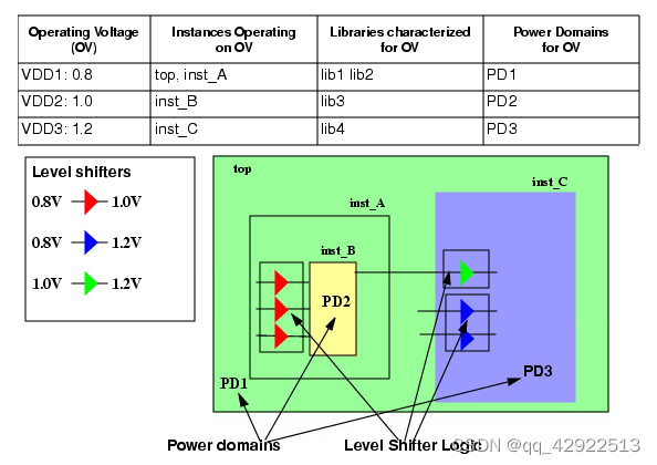
注:在后文中,图中红色level shifters被认为放到inst_B中,而不是inst_A中。
2.1 指定libraries
goup libraries that are characterized for specific set of operating conditions
define_library_set -name set1 -libraries {lib1 lib2}
define_library_set -name set2 -libraries {lib3}
define_library_set -name set3 -libraries {lib4}
注:
在将level_shifter cells放置在destination端的情况下,包含有level_shifter cells的PMK库应根据voltage2(即VDD)的值定义在相应的library set中。不知此理解是否正确,会在后续使用中进行确认,同时也希望看到本贴的有相关经验的大佬在评论区指点一下!提前感谢!!!
2.2 指定要使用的level shifter cells
define_level_shifter_cell -cells LVLLHEHX* \-library_set \-input_voltage_range 0.8 \-output_voltage_range 1.0 \-input_power_pin VDDI \-output_power_pin VDD \-direction up \-ground VSS \-valid_location from相关选项说明:
#for power voltage shifting
-input_power_pin LEF_power_pin
-output_power_pin LEF_power_pin
-ground LEF_ground_pin#for ground voltage shifting
-input_ground_pin LEF_ground_pin
-output_ground_pin LEF_ground_pin
-power LEF_power_pin
注:当不同的define使用同一个library_set中的cell时,cell名称应有所区分,否则后面定义的cell会覆盖掉前面的cell。
2.3 声明CPF文件中描述的设计
set_design top2.4 指定power domains
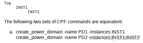
create_power_domain -name PD1 -default
create_power_domain -name PD2 -instances inst_B
create_power_domain -name PD3 -instances inst_C
CPF要求顶部模块属于default power domain。
2.5 指定设计中使用的工作电压
create_nominal_condition -name low -voltage 0.8
create_nominal_condition -name medium -voltage 1.0
create_nominal_condition -name high -voltage 1.2
2.6 将nominal condition与power domain相关联
create_power_mode -name PM -domain_conditions {PD1@low PD2@medium PD3@high} -default
#domain_condition_list格式:  power_domain_name@nominal_condition_name
CPF要求指定一种power mode作为default power mode。
2.7 指定要用于nominal condition的libraries
update_nominal_condition -name low -library_set set1
update_nominal_condition -name medium -library_set set2
update_nominal_condition -name high -library_set set3
2.8 指定创建level shifter logic的rules
create_level_shifter_rule -name lsr1 -from PD1 -to PD2
create_level_shifter_rule -name lsr2 -from PD2 -to PD3
create_level_shifter_rule -name lsr3 -from PD1 -to PD3
2.9 指定power约束 (可选)
set_power_target -leakage float -dynamic float2.10 指定timing约束 (可选)
update_power_mode -name PM -sdc_files sdc_file2.11 指定activity information (可选)
update_power_mode -name PM -activity_file file -activity_file_weight weight
#file format:VCD TCF SAIF
#如果设计有多个power modes,可以指定每个modes活动的相对weight,以便进行优化。由于MSV设计只有一种power mode,所以文件的weight必须为100。
2.12 使用实现信息更新rules
update_level_shifter_rules -names {lsr1 lsr2 lsr3} -location toThe following information is needed for physical implementation
2.13 指定全局的接电和接地nets
create_ground_nets -nets net_list
create_power_nets -nets net_list -voltage string
2.14 指定全局连接
create_global_connection -net net -pins pin_list2.15 指定接电和接地路由的附加信息
update_power_domain -name domain -primary_power_net net3、flow steps
3.1 read the target libraries
只有在CPF文件中没有指定库时才需要此步骤。如果在CPF文件中指定了库,则在读取CPF文件后读取LEF库。
3.2 read the power intent
read_power_intent -cpf -module top_module_name cpf_file对于在CPF文件中指定的库,必须在CPF文件中提供完整的或相对的文件名路径,因为CPF文件意味着可以由多个工具读取。 read_power_intent命令不使用init_lib_search_path属性来加载使用define_library_set命令在CPF文件中定义的库。
3.3 apply the power intent
After reading in the design and elaborating the design, you need to apply the power intent.
apply_power_intent3.4 check the power intent
check_cpfTo run this command you need to have access to versioon 7.1 (or later) of the Conformal Low Power software.
3.5 commit the power intent
commit_power_intent在这个时候,Genus-LP引擎插入level shifters。
要报告设计中插入的所有电平移位器,使用以下命令:
report power_intent_instances -level_shifter_only3.6 verify added power logic
verify_power_structure -level_shifterTo run this command you need to have access to versioon 7.1 (or later) of the Conformal Low Power software.
3.7 set timing, design, and power constraints
四、Using CPF for Design Using Power Shutoff Methodology
1、overview
使用电源关闭(PSO)实现的设计是一种可以根据需要打开和关闭某些部分以节省泄漏和动态功率的设计。
1.1 power domain
逻辑块(分层实例)、叶实例和引脚使用相同的主电源,并且可以同时打开或关闭,则它们属于相同的power domain。
power domain分类:
电源域从未关机,称为unswitched domain。可下电的域称为switchable domain。CPF区分internal switchable domain和on-chip controlled external switchable domain。
(1)unswitched domain
Specify the create_power_domain command without the -shutoff_condition or the -external_controlled_shutoff options.
(2)internal switchable domain
Specify the condition that causes the power domain be powered down through the -shutoff_condition option of the creat_power_domain command.
Specify the domain from which the switchable domain (or the power switch) gets its power supply through the -base_domains option of the create_power_domain command.
(3)on-chip controlled external switchable domain
该域可以通过外部电源开关(芯片外部)断电,但外部开关由芯片上的信号控制。
Specify the condition that causes the power domain be powered down through the -shutoff_condition option together with the -external_controlled_shutoff option of the create_power_domain command.
当一个域可切换时,它通过内部或外部power switch logic从另一个电源域派生其power。假如,power domain PD2从power domain PD1派生其power,则称PD1为PD2的secondary(base)域,PD2被称为primary(derived)域。
当定义一个电源域(primary)时,可以指定它的secondary域以及在什么情况下该域(primary)将被关闭。
1.2 power mode
在设计中,一些电源域处于打开状态,一些电源域处于关闭状态,这种稳定状态被称为power mode。在power mode中,每个功率域在特定的标称条件下工作。不同的时序约束可以与每个power mode相关联。
1.3 isolation cells
为防止未知状态从断电的功率域传播到保持开着的功率域,需要在断电的功率域边界处设置isolation cells。大多数情况下,isolation cells被插入到断电域的输出边界。
CPF可以描述许多不同类型的isolation cells。以下是最典型的isolation cells:
(1)isolation cell to be placed in the unswitched domain
(2)isolation cell to be used in a gound switchable domain
(3)isolation cell to be used in a power switchable domain
define_isolation_cell -cells cell_list -library_set library_set \-power_switchable \-power VDD -ground VSS \-enable ENB(EN) \-valid_location from-power_switchable:识别对应的LEF单元中的POWER引脚,该单元在电源关闭模式下被关闭。
-power:如果该选项与-powre_switchable选项一起指定,则表示在电源关闭模式下打开的电源对应的LEF单元的POWER pin。
-ground:如果该选项与-powre_switchable选项一起指定,则表示指定cell的GROUND pin。
(4)isolation cell to be used in a power or ground switchable domain
(5)isolation cells without followpins that can be placed in any domain
(6)isolation cells without an enable pin
(7)isolation clamp cell
(8)isolation-level shifter combo cell
1.4 state retention cells
为了方便断电块恢复正常操作,可以对一些sequential cells使用state retention cells,以便在断电之前保持其先前的状态。
State Retention Cells分类:
(1)State Retention Cell with Save Control
要建模一个状态保持单元,当电源打开时控制引脚激活时保存当前值,当电源关闭时保留保存值,当电源打开时恢复保存值,使用以下命令选项:
(2)State Retention Cell with Restore Control
要模拟一个状态保持单元,当控制引脚失效时保存当前值,当控制信号激活时恢复保存的值,使用以下命令选项:
define_state_retention_cell -cells -restore_function expression
#-restore_function:指定恢复引脚的极性,使保留单元能够在退出电源关闭模式后恢复保存的值。表达式仅限于引脚名称和引脚名称的反转。仅包含引脚名称的表达式表示an active high polarity。包含引脚名称反转的表达式表示an active low polarity。
(3)State Retention Cells with Save and Restore Control
(4)State Retention Cells without Save or Restore Control
1.5 power switch cells
在电源域内,需要增加power switch logic (for internal switchable domain)或使用external power shut-off method (for external switchable domain),才能接通和断开电源与门的连接。
power switch cells分类:
要连接和断开internal switchable domain的电源(或地)供应,必须添加power switch logic。
(1)single stage power switch cell
控制internal switchable domain逻辑的主电源的单晶体管。
define_power_switch_cell -cells \-stage_1_enable expression \-type header \-power \-power_switchable-power:识别相应LEF单元的输入POWER pin。
-power_switchable:识别相应LEF单元的输出POWER pin,该单元必须连接到可切换的powr net。
(2)single stage ground switch cell
控制internal switchable domain逻辑的主地电源的单晶体管。
(3)dual-stage power switch
电源开关具有一个弱和强晶体管,用于控制internal switchable domain逻辑的主电源。
(4)dual-stage ground switch
接地开关,带有一个弱和强晶体管,用于控制internal switchable domain逻辑的主接地电源。
1.6 special control signals
特殊的控制信号用于关闭电源域,使能状态保持,控制电源开关逻辑的工作和使能隔离。
1.7 primary and secondary domain
一个电源域中的大多数实例由同一电源驱动。对于switchable domain,实例所属的primary电源域的主电源和接地nets为单元的电源和接地pins (follow-pins)提供电源。另一方面,isolation ceslls和state retention ceslls由多个电源驱动。这些特殊的低功耗实例至少有两组电源和接地引脚,因此与两个电源域相关联:primary域是为它们的primary电源和接地pins提供电源的域;secondary域是其(域)主电源和接地nets为特殊低功率实例的secondary电源和接地pins提供电源的域。
2、flow steps

注:本文中,isolation cells被放置在上电域的输入边界。
2.1 specifying the libraries
We assume only one main power supply, which implies that the definition of one library set is sufficient.
define_library_set -name set1 -libraries {lib1 lib2}2.2 specifying the isolation cells to use
define_isolation_cell -cells A2BISO* -enable ENB -valid_location to -library_set set#-valid_location:指定隔离单元的有效位置。
-from:指示cell只能用于“关到开”隔离,并且必须插入与原始电源域兼容的电源域。它通常依靠其primary power and ground pins来实现正常功能,依靠其secondary power or ground pins来提供隔离功能。
-to:指示该单元必须插入与目标电源域兼容的电源域中,因为其正常功能和隔离功能依赖于其primary power and ground pins。只能将这种类型的单元格用于“关到开”隔离。
2.3 specifying the always-on cells
Always-on cells是一种特殊的单元,它的电源必须持续接通,即使在电源域中其余逻辑的电源关闭时也是如此。Always-on cells的用法如下:
(1)驱动处于断电状态的域内state retention cells的控制信号。
(2)与插入已关闭的电源域中的isolation cells结合使用,可确保隔离单元的使能引脚(enable)的驱动器永远不会关闭。
define_always_on_cell -cells GPAND2*2.4 specifying the state retention cells to be used
define_state_retention_cell -cells -restore_function RETN
#该命令表示,当恢复引脚RETN设置为1时,指定单元的状态将恢复到退出电源关闭模式后保存的值。
2.5 specifying the power switch cells to be used
define_power_switch_cell -cells -stage_1_enable SLEEP -type header#-stage_1_enable:如果只指定了stage1,当-stage_1_enable选项的表达式求值为true时,开关将打开。2.6 declaring the design described in the CPF file
set_design top2.7 specifying the power domains
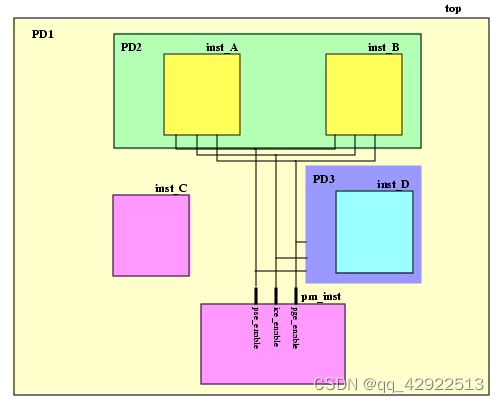
create_power_domain -name PD1 -default
create_power_domain -name PD2 -instances {inst_A inst_B} \-shutoff_condition pse_enable[0] -base_domains PD1
create_power_domain -name PD3 -instances inst_D \-shutoff_condition pse_enable[1] -base_domains PD1
CPF要求顶部模块属于default power domain。
2.8 specifying the operating voltage used in the design
create_nominal_condition -name off -voltage 0
create_nominal_condition -name on -voltage 1.1
2.9 specifying the static behavior in each power mode
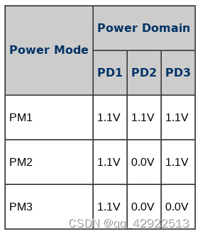
create_power_mode -name PM1 -domain_conditions {PD1@on PD2@on PD3@on} -default
create_power_mode -name PM2 -domain_conditions {PD1@on PD3@on}
create_power_mode -name PM3 -domain_conditions {PD1@on}
CPF要求指定一种power mode作为default power mode。
如果在域条件列表中未指定某个域,则认为该域在指定模式下关闭。在定义power mode时,建议不要依赖默认行为,并指定所有的电源域。
2.10 specigying the libraries to use for a condition
update_nominal_condition -name on -library_set set12.11 specifying the rules to create isolation logic
create_isolation_rule -name iso1 -from PD2 \-isolation_condition ice_enable[0] -isolation_output hige
create_isolation_rule -name iso2 -to PD1 \-isolation_condition ice_enable[1] -isolation_output hige-isolation_condition:Specifies the condition when the selected domain crossings should be isolated.
-isolation_output: Controls the output value at the output of the isolation gates when the isolation condition is true.
2.12 specifying the rules to create state retention logic
create_state_retention_rule -name st1 -domain PD2 -restore_edge !pge_enable[0]
create_state_retention_rule -name st2 -domain PD3 -restore_edge !pge_enable[1]#-restore_edge expr:当表达式expr从false变为true时,恢复状态。
2.13 指定power约束 (可选)
set_power_target -leakage float -dynamic float2.14 指定timing约束 (可选)
update_power_mode -name PM1 -sdc_files sdc_file2.15 指定activity information (可选)
update_power_mode -name PM1 -activity_file file -activity_file_weight weight
#file format:VCD TCF SAIF
#如果设计有多个power modes,可以指定每个modes活动的相对weight,以便进行优化。
2.16 使用实现信息更新rules
update_isolation_rules -names iso1 -location to
update_isolation_rules -names iso2 -location to
The following information is needed for physical implementation
参考
IC设计基础系列之低功耗篇1:(数字IC)低功耗设计入门(一)——低功耗设计目的与功耗的类型_说的低功耗ic指的是什么意思_Times_poem的博客-CSDN博客
论综合:为什么做physical aware synthesis (qq.com)
芯片设计进阶之路——低功耗深入理解(一) - 知乎 (zhihu.com)
本文来自互联网用户投稿,文章观点仅代表作者本人,不代表本站立场,不承担相关法律责任。如若转载,请注明出处。 如若内容造成侵权/违法违规/事实不符,请点击【内容举报】进行投诉反馈!