HDLBits——Arithmetic Circuits
HDLBits——Arithmetic Circuits
Problem 65 : Half adder (Hadd)
Requirement:
本题中需要实现一个 2 进制 1bit 加法器,加法器将输入的两个 1bit 数相加,产生两数相加之和以及进位。
Solution:
module top_module( input a, b,output cout, sum );assign {cout,sum} = a + b;endmodule
Problem 66 : Full adder (Fadd)
Requirement:
本题中需要实现一个 2 进制 1bit 全加器,全加器与上一题中的加法器的区别在于需要累加来自前级的进位。
Solution:
module top_module( input a, b, cin,output cout, sum );assign {cout,sum} = a + b + cin;endmodule
Timing Diagram:

Problem 67 : 3-bit binary adder(Adder3 )
Requirement:
本题中需要通过实例化 3 个全加器,并将它们级联起来实现一个位宽为 3 bit 的二进制加法器。其实 3 bit 的加法器 cout 也只需要一位就够了,直接 assign {cout,sum} = a + b + cin。这里给了三位是暗示包括了每一位上的进位,即需要例化 3 个全加器模块,而不是一条 assign 语句。
Solution:
module top_module( input [2:0] a, b,input cin,output [2:0] cout,output [2:0] sum );add1 add1(a[0],b[0],cin,cout[0],sum[0]); add1 add2(a[1],b[1],cout[0],cout[1],sum[1]);add1 add3(a[2],b[2],cout[1],cout[2],sum[2]); endmodulemodule add1( input a, b, cin,output cout, sum );assign {cout,sum} = a + b + cin;endmodule//also
assign sum = a ^ b ^ cin;
assign cout = a&b | a&cin | b&cin;
Timing Diagram:

Problem 68 : Adder (Exams/m2014 q4j)
Requirement:
实现下图中的电路,一个 4-bit 全加器,FA:full adder 全加器。

Solution:
module top_module (input [3:0] x,input [3:0] y, output [4:0] sum);assign sum = x + y;endmodule
verilog 的语法会自动将 x+y 扩展成 5 bit 数,但如果使用位连接符 {x+y},那么结果就会被限制为 4 bit 数。
Problem 69 : Signed addition overflow (Exams/ece241 2014 q1c)
Requirement:
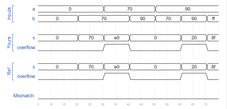
有符号数相加的溢出问题,实现一个 2 进制 8bit 有符号数加法器,加法器将输入的两个 8bit 数补码相加,产生相加之和以及进位。
Solution:
方法一:判断变号与否。
有符号数溢出有两种情况:一是正正相加,产生负数;另一种情况是负负相加,产生正数。
module top_module (input [7:0] a,input [7:0] b,output [7:0] s,output overflow
); //assign s = a + b;assign overflow = (a[7]&b[7]&~s[7])|(~a[7]&~b[7]&s[7]);endmodule方法二:判断数值位和符号位是否同时进位(双符号位)。
module top_module (input [7:0] a,input [7:0] b,output [7:0] s,output overflow
); wire [8:0] t;assign t = {a[7],a} + {b[7],b};assign s = t;assign overflow = t[8]^t[7];endmodule
Timing Diagram:
Problem 70 100-bit binary adder
Requirement:
题目要求我们创建一个 100bit 的二进制的加法器,该电路共包含两个 100bit 的输入和一个 cin, 输出产生 sum 和 cout。
Solution:
module top_module( input [99:0] a, b,input cin,output cout,output [99:0] sum );assign {cout,sum} = cin + a + b;endmodule虽然这样就足够简单了,但还是练习一下 for 循环吧。
always-for:
module top_module( input [99:0] a, b,input cin,output reg cout,output reg [99:0] sum );reg [99:0] cout100;integer i;always @(*) begin{cout100[0],sum[0]} = a[0] + b[0] + cin;for(i=1;i<100;i=i+1)begin{cout100[i],sum[i]} = a[i] + b[i] + cout100[i-1];endcout = cout100[99];endendmodulegenerate-for:
module top_module( input [99:0] a, b,input cin,output cout,output [99:0] sum );wire [99:0] cout100;assign {cout100[0],sum[0]} = a[0] + b[0] + cin;genvar i;generatefor(i=1;i<100;i=i+1)begin:add100assign {cout100[i],sum[i]} = a[i] + b[i] + cout100[i-1];endendgenerateassign cout = cout100[99];endmodulePS:例化时 begin 块要有标签名的原因:generate 循环中例化的模块名为add100[1].例化名,add100[2].例化名.……add100[99].例化名,这样就算例化名里没有 i,也不怕重复。
Problem 71 4-digit BCD adder
Requirement:
在本题中,题目给我们提供了一个 BCD 加法器名字为 bcd_fadd, 输入为两个 4bitBCD 码,一个 cin,产生输出为 sum 和 cout。
已知:
module bcd_fadd {input [3:0] a,input [3:0] b,input cin,output cout,output [3:0] sum );
Solution:
module top_module( input [15:0] a, b,input cin,output cout,output [15:0] sum );wire [4:0] cout16;assign cout16[0] = cin;genvar i;generatefor(i=0;i<4;i=i+1)begin:add16bcd_fadd bcd_fadd_i(a[4*i+:4],b[4*i+:4],cout16[i],cout16[i+1],sum[4*i+:4]);endendgenerateassign cout = cout16[4];endmodule错过:不管多少位宽的加法,进位永远只有一位。
唯一的感受:困
本文来自互联网用户投稿,文章观点仅代表作者本人,不代表本站立场,不承担相关法律责任。如若转载,请注明出处。 如若内容造成侵权/违法违规/事实不符,请点击【内容举报】进行投诉反馈!