暑期实习学习经历:基于ensp传统园区改造升级
1.前言
1.1
大三暑假,几经波折考完驾照后,在爸妈的推荐下来到深圳某公司实习学习。我本科学的是网络工程专业,被分到了智慧城市运营部。
师傅在了解了我的简单情况后先是给了我一张简单的拓扑做了一下,然后改编了一道HCIE的实验题让我练习。
HCIE只有一道实验大题,主要分4部分:
一、传统园区改造
二、云管园区campus及SDWAN
三、广域承载网(可能考mpls或者SRv6)
四、python自动化
师傅给我的题是改编过后第一部分,因为旧版ensp不支持准入和堆叠的实现,就把这两个需求去掉了。由于我本身还处在IP的学习阶段,因此这拓扑的难度对我来说还是蛮大的。好在经过师傅两三周的教学和指导,我基本消化了这些知识点。感谢师傅!
想着这次学习经历对将来中小型企业网络工作有着重大帮助,也是我人生路上的一个里程碑(第一次实习),故在朋友的建议下写了这第一篇blog来记录一下这次学习的经历。有什么错误和不足之处希望朋友们不吝赐教。
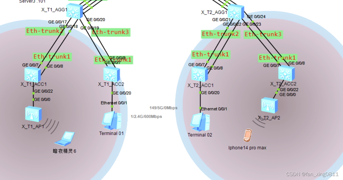
2.拓扑图
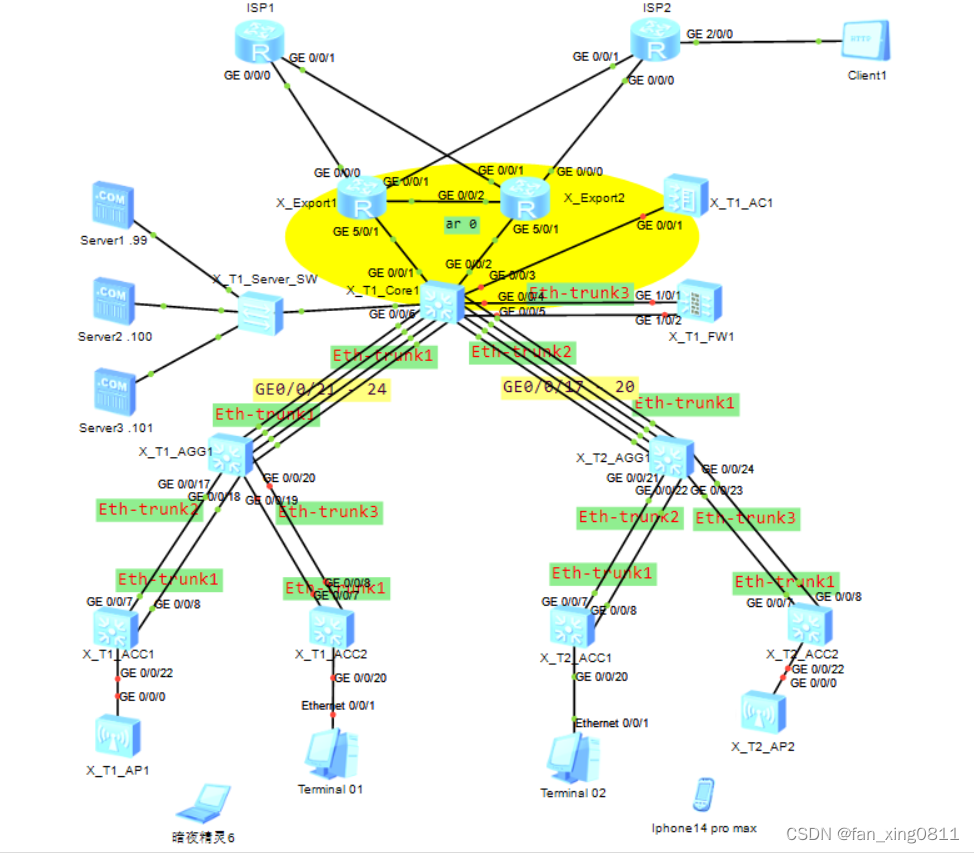
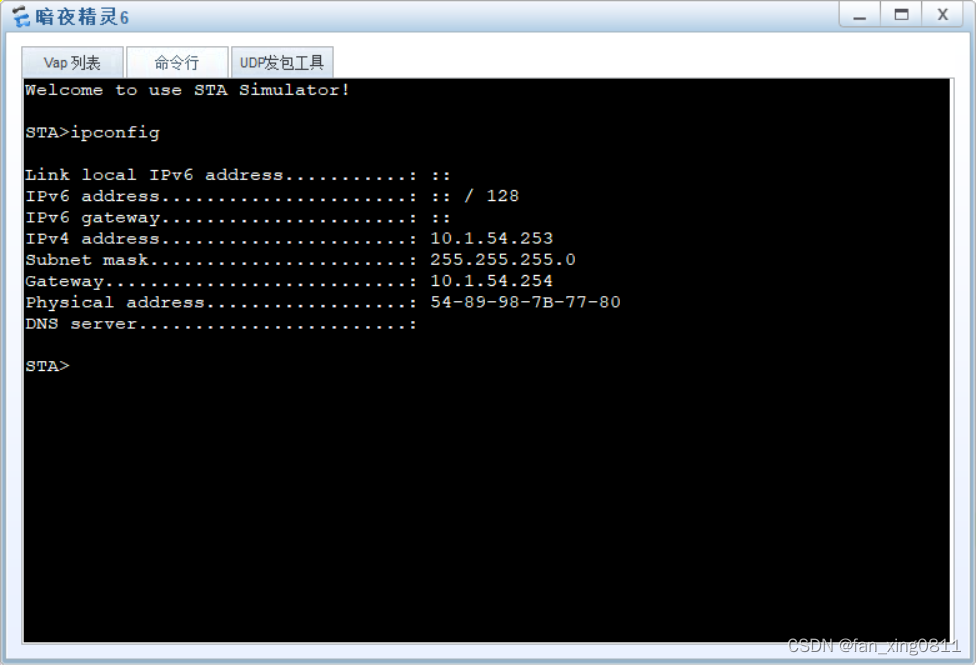
P.s:下面的暗夜精灵6和iphone14promax是在检查wlan时整活弄上去的终端(
3.需求方面
3.1 Eth-trunk: X_T1_CORE1 分别与汇聚交换机、防⽕墙之间部署 Eth-trunk;⼯作模式为 LACP,设备 间所有物理链路均作为成员链路,且链路必须处于选中状态。 3.2 基础业务 (VLAN、IP、DHCP、路由) 根据所在部⻔,接⼊⽅式,终端类型等因素将终端⽤户划分成 7 类对象,参考表 1-1《X 市园区终端接⼊规划表》 3.2.1、市场部、采购部从 X_T1_ACC1 和 X_T1_ACC2 的 G0/0/22,G0/0/20接⼊⽹络。 财务部、⼈⼒部从 X_T2_ACC1 和 X_T2_ACC2 的 G0/0/20,G0/0/22 接⼊⽹络。 3.2.2.除服务器外,其它所有用户均通过DHCP获取ip地址与网关信息,X_T1_Core1 为 DHCP 服务器 3.2.3、⽹关设备均以 VLANIF 作为⽤户⽹关,IP 地址为 10.1.X.254,X 为⽤户所在 VLAN。 3.3 OSPF 所有三层设备之间部署多区域 OSPF。 1. 两台出⼝路由器与核⼼交换机之间的链路属于⻣⼲⽹络,终端访问 Internet 流量由 出⼝两台路由器共同分担。 2. 核⼼交换机与 AC 之间的链路属于⻣⼲⽹格。 3. 根据⽹络隔离需求,将内部⽹络与访客⽹络分别划分到 OSPF 的区域 1 和区域 2。 3.4 ⽹络隔离 1. 在 X_T1_CORE1 上通过部署两个 VPN 实例实现内部、访客流量隔离。 1.1 实例名称为 Employee 与 Guest,RD 分别为 65001:1 和 65001:2; 1.2 表 1-1 中,外部⽆线⽤户属于 Guest,其它所有⽹络都属于 Employee。 2. 防⽕墙 X_T1_FW1,使⽤虚拟系统与 X_T1_CORE1 上的两个 VPN 实例 Guest 和 Employee 进⾏对接。 2.1 虚拟系统的名称与其对接的 VPN 实例名称保持⼀致; 2.2 VLAN204,VLAN206 属于实例 Employee, VLAN204 划分进安全区域 Untrust, VLAN206 划分进安全区域 Trust; 2.3 VLAN205,VLAN207 属于实例 Guest;VLAN205 划分进安全区域 Untrust, VLAN207 划分进安全区域 Trust。 2.4 虚拟系统 Employee 与虚拟系统 Guest 和 X_TI_CORE1 之间的链路分别属于 OSPF 的区域 1 和区域 2。 2.5 使⽤ IP-Prefix 作为过滤器进⾏路由过滤,Employee 与 Guest 之间不学习对⽅ 终所在⽹段的明细路由与对应的 3 类 LSA。 2.6 在不使⽤策略路由的前提下,跨 OSPF 区域的流量必须经过防⽕墙。 3.5 WLAN 需求 1、 X_T1_AP1 已在 AC 上线且正常提供⽆线服务,X_T2_AP1 和 X_T1_AP1 在共同管 理 VLAN 上线并提供相同的⽆线服务,即延续当前的 WLAN 相关配置: 1.1 内部⽆线⽤户使⽤的 SSID 为 X_Employee_010,密码为 Huawei@123 1.2 外部⽆线⽤户使⽤的 SSID 为 X_Guest_010,密码为 Huawei@123 1.3 ⽆线⽤户数据采⽤集中转发的机制,统⼀由 AC 进⾏数据转发 2、 当前⽹络分别为内部与外部⽆线⽤户预留 10.1.51.0/24(vlan51)与 10.1.101.0/24 vlan101),经常出现由于 DHCP 服务器地址不⾜导致⽤户⽆法正常接⼊⽆线⽹ 络的情况。现需要根据表 1-1 扩充可⽤地址数量。同时还需尽量保证同⼀⽤户接 ⼊⽹络时, IP 地址不发⽣改变。 3.6 出⼝⽹络 1. 新增出⼝路由器 X_T1_Export2,采⽤双 Internet 线路实现上⽹流量的负载分担 1.1 GE0/0/1 采⽤静态配置 IP 地址:10.255.3.1/24,⽹关为 10.255.3.254 1.2 GE0/0/0 采⽤静态配置 IP 地址:10.255.4.1/24,⽹关为 10.255.4.254 2. 所有⽤户通过 X_T1_Export2 路由器访问 Internet 时,需要通过 NAT 替换私⽹ IP 地址 2.1 对所有通过防⽕墙策略的 IP 报⽂进⾏源地址与端⼝转换; 2.2 Export2 的 GE0/0/1 使⽤当前接⼝地址作为转换后的地址; 2.3 Export2 的 GE0/0/0 使⽤地址池(10.255.4.2 - 10.255.4.100)替换私⽹ IP 地 址和端⼝; 2.4 X 园区内⽹服务器(10.1.60.101)向外提供 WEB 服务(端⼝号为 80),公⽹ ⽤户通过 10.255.4.1 的 8081 号端⼝访问该服务器。 3.7 ⽹络安全 1、防⽕墙上配置安全策略实现⽤户访问权限的控制 1.1 仅采购部(11-15),市场部(21-25),内部⽆线⽤户(51-55),外部⽆线⽤户 (101-105) 可以访问 Internet; 1.2 内部⽆线⽤户仅可以访问服务器⽹段的某⼀服务器,IP 为 10.1.60.100; 1.3 外部⽆线⽤户仅可以访问服务器⽹段中的 HTTP 服务(名为 Guest_Service), IP 为 10.1.60.99,端⼝为 3389(TCP)。 2、安全策略需按照下列规则配置: 2.1 必须包含源、⽬的安全区域 2.2 若包含特定服务,需使⽤系统预定义服务或⾃定义服务(service-set)表示 3、外部⽆线⽤户访问 Guest_Service 服务的流量需要直接在 Guest 和 Employe 两 个虚拟系统之间转发。 3.1 Guest 和 Employee 两个虚拟系统的 Virtual-if 属于 untrust 安全区域,IP 地 址分别为 10.1.200.254/32 和 10.1.200.253/32; 3.2 仅当外部⽆线⽤户访问 10.1.60.99 时,流量直接在虚拟系统之间转发。 3.8 引导流量转发 1. 由于内部⽆线业务属于 Employee 实例,服务器区也属于 Employee 实例,同实例 之间的流量⽆法被路由引导到 FW 上,所以需要在内部⽆线⽹关的 VLANIF 下,配 置 traffic-redirect 重定向流量到 FW。 2. 内⽹ WEB 服务器通过 Core1 的 public 路由表回包给外⽹⽤户,需要通过 PBR 把回包流量送到 X_Export2,否则就可能通过等价的缺省路由发送到 X_Export1,导 致业务不通。 看完这些需求是否感觉头晕目眩无从下手的样子?没关系!我刚开始也是这样!接下来我们一个一个讲!3.1 Eth-trunk
X_T1_CORE1 分别与汇聚交换机、防⽕墙之间部署 Eth-trunk;⼯作模式为 LACP,设备 间所有物理链路均作为成员链路,且链路必须处于选中状态。3.1.1Eth-trunk实现:
使用lldp协议发现X_T1_Core1与X_T1_AGG1/X_T2_AGG1之间的链路状况(图中已标出接口,实际情况下需要使用lldp协议),根据lldp的输出结果,绑定相应的接口进入Eth-trunk。
这里以X_T1_Core1与X_T1_AGG1之间的Eth-trunk1配置举例:
后续依次在核心与两台汇聚和防火墙之间、四台接入和汇聚之间添加Eth-trunk。( 一定要记得在对端也添加Eth-trunk并且设置模式为lacp,别忘了!要不然接口会处于down状态,后续做wlan时就因为有个接口没有启用lacp,检查了半天才看出这个小问题)
sy [X_T1_Core1]interface Eth-Trunk 1
[X_T1_Core1-Eth-Trunk1]mode lacp-static[X_T1_Core1-Eth-Trunk1]trunkport GigabitEthernet 0/0/21 to 0/0/24
3.2 基础业务(VLAN、IP、DHCP、路由)
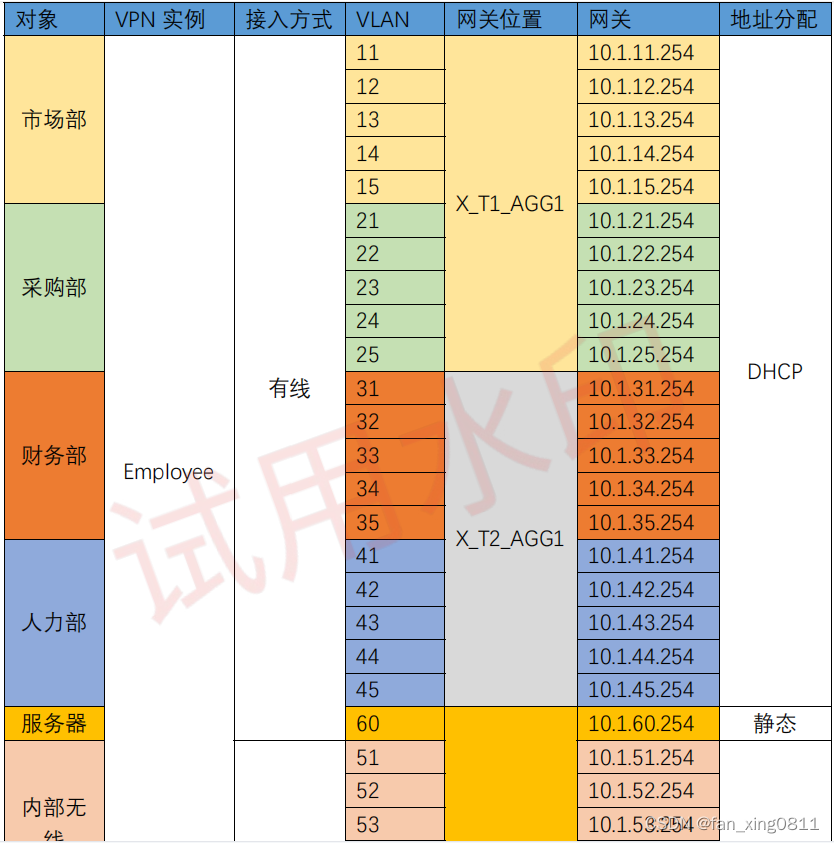
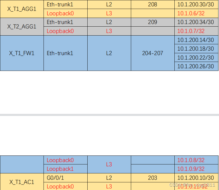
根据所在部⻔,接⼊⽅式,终端类型等因素将终端⽤户划分成 7 类对象,参考表 1-1《X 市园区终端接⼊规划表》
表 1-1《X 市园区终端接⼊规划表》:

3.2.1 配置VLAN:
在所有设备上配置VLAN,并允许相应的VLAN通过trunk链路。
1.在X_T1_Core1上:
2.在X_T1_AGG1上:
sy [X_T1_Core1]vlan batch 51 to 55 60 100 to 105 201 to 209
3.在X_T1_ACC1和X_T1_ACC2上(以ACC1为例):sy [X_T1_AGG1]vlan batch 11 to 15 21 to 25 100 208
4.在X_T2_AGG1上:sy [X_T1_ACC1]vlan batch 11 to 15 21 to 25 100
5.在X_T2_ACC1和X_T2_ACC2上(以ACC1为例):sy [X_T2_AGG1]vlan batch 31 to 35 41 to 45 100 209
6.在X_T1_FW1上: P.s.:华为防火墙缺省状态登录账号和密码是:admin Admin@123sy [X_T2_ACC1]vlan batch 31 to 35 41 to 45 100
7.在AC上:sy [X_T1_FW1]vlan batch 204 to 207
sy [X_T1_AC1]vlan batch 51 to 55 100 to 105 203
3.2.2 在Trunk上允许相应的VLAN:
3.2.2.1:在X_T1_Core1上:
sy [X_T1_Core1]interface Eth-Trunk 1
[X_T1_Core1-Eth-Trunk1]port link-type trunk
[X_T1_Core1-Eth-Trunk1]port trunk allow-pass vlan 100 208
请注意:为什么Eth-trunk 1和2不需要透传四个部门的业务VLAN呢?因为VLAN止于二层,汇聚并不需要把业务VLAN再透传给核心了。 至于为什么需要透传VLAN100,这个后续wlan需求时会讲到。sy [X_T1_Core1]interface Eth-Trunk 2 [X_T1_Core1-Eth-Trunk2]port link-type trunk [X_T1_Core1-Eth-Trunk2]port trunk allow-pass vlan 100 209
//链接防火墙的链路sy [X_T1_Core1]interface Eth-Trunk 3 [X_T1_Core1-Eth-Trunk3]port link-type trunk [X_T1_Core1-Eth-Trunk3]port trunk allow-pass vlan 204 to 207
//链接AC的链路,允许无线VLAN的流量sy [X_T1_Core1]interface GigabitEthernet 0/0/3 [X_T1_Core1-GigabitEthernet0/0/3]port link-type trunk [X_T1_Core1-GigabitEthernet0/0/3]port trunk allow-pass vlan 51 to 55 100 101 to
105 203
3.2.2.2:在X_T1_AGG1上:
sy [X_T1_AGG1]interface Eth-Trunk 1 [X_T1_AGG1-Eth-Trunk1]port link-type trunk [X_T1_AGG1-Eth-Trunk1]port trunk allow-pass vlan 100 208
sy [X_T1_AGG1]interface Eth-Trunk 2 [X_T1_AGG1-Eth-Trunk2]port hybrid tagged vlan 11 to 15 21 to 25 100
//这里Eth-trunk2和3改为hybrid模式本来是为了后续准入的需求,其实trunk也可以。sy [X_T1_AGG1]interface Eth-Trunk 3 [X_T1_AGG1-Eth-Trunk2]port hybrid tagged vlan 11 to 15 21 to 25 100
3.2.2.3:在X_T1_ACC1、X_T1_ACC2上(以ACC1为例):
sy [X_T1_ACC1]interface Eth-Trunk 1 [X_T1_ACC1-Eth-Trunk1]port link-type hybrid //可以不写,华为交换机eth-trunk端口缺省端口类型就是hybrid [X_T1_ACC1-Eth-Trunk1]port hybrid tagged vlan 11 to 15 21 to 25 100
3.2.2.4:在X_T2_AGG1上:
sy [X_T2_AGG1]interface Eth-Trunk 1 [X_T2_AGG1-Eth-Trunk1]port link-type trunk [X_T2_AGG1-Eth-Trunk1]port trunk allow-pass vlan 100 209
sy [X_T2_AGG1]interface Eth-Trunk 2 [X_T2_AGG1-Eth-Trunk2]port hybrid tagged vlan 31 to 35 41 to 45 100
sy [X_T2_AGG1]interface Eth-Trunk 3 [X_T2_AGG1-Eth-Trunk2]port hybrid tagged vlan 31 to 35 41 to 45 100
3.2.2.5:在X_T2_ACC1、X_T2_ACC2上(以ACC1为例):
sy [X_T2_ACC1]interface Eth-Trunk 1 [X_T2_ACC1-Eth-Trunk1]port link-type hybrid //可以不写,华为交换机eth-trunk缺省接口类型就是hybrid [X_T2_ACC1-Eth-Trunk1]port hybrid tagged vlan 31 to 35 41 to 45 100
3.2.2.6:在X_T1_FW1上:
sy [X_T1_FW1]interface Eth-Trunk 1 [X_T1_FW1-Eth-Trunk1]portswitch [X_T1_FW1-Eth-Trunk1]port link-type trunk [X_T1_FW1-Eth-Trunk1]port trunk allow-pass vlan 204 to 207
3.2.2.7:在X_T1_AC上:
sy [X_T1_AC1-GigabitEthernet0/0/1]port link-type trunk [X_T1_AC1-GigabitEthernet0/0/1]port trunk allow-pass vlan 51 to 55 100 101 to
[X_T1_AC1]interface GigabitEthernet 0/0/1
105 203
3.2.3 配置DHCP服务及网关地址,关联相应的VPN-Instance(无线网关地址均配置在核心上)
3.2.3.1:在X_T1_Core1上:
a:配置VPN实例,设置RD值(后续需求会提到),以及使能DHCPb:配置DHCP地址池sy [X_T1_Core1]dhcp enable [X_T1_Core1]ip vpn-instance Employee [X_T1_Core1-vpn-instance-Employee]route-distinguisher 65001:1 [X_T1_Core1]ip vpn-instance Guest [X_T1_Core1-vpn-instance-Guest]route-distinguisher 65001:2
[X_T1_Core1]ip pool shichang11 [X_T1_Core1-ip-pool-shichang11]vpn-instance Employee [X_T1_Core1-ip-pool-shichang11]gateway-list 10.1.11.254 [X_T1_Core1-ip-pool-shichang11]network 10.1.11.0 mask 24
[X_T1_Core1]ip pool shichang12 [X_T1_Core1-ip-pool-shichang12]vpn-instance Employee [X_T1_Core1-ip-pool-shichang12]gateway-list 10.1.12.254 [X_T1_Core1-ip-pool-shichang12]network 10.1.12.0 mask 24
[X_T1_Core1]ip pool shichang13 [X_T1_Core1-ip-pool-shichang13]vpn-instance Employee [X_T1_Core1-ip-pool-shichang13]gateway-list 10.1.13.254 [X_T1_Core1-ip-pool-shichang13]network 10.1.13.0 mask 24
[X_T1_Core1]ip pool shichang14 [X_T1_Core1-ip-pool-shichang14]vpn-instance Employee [X_T1_Core1-ip-pool-shichang14]gateway-list 10.1.14.254 [X_T1_Core1-ip-pool-shichang14]network 10.1.14.0 mask 24
[X_T1_Core1]ip pool shichang15 [X_T1_Core1-ip-pool-shichang15]vpn-instance Employee [X_T1_Core1-ip-pool-shichang15]gateway-list 10.1.15.254 [X_T1_Core1-ip-pool-shichang15]network 10.1.15.0 mask 24
[X_T1_Core1]ip pool caigou21 [X_T1_Core1-ip-pool-caigou21]vpn-instance Employee [X_T1_Core1-ip-pool-caigou21]gateway-list 10.1.21.254 [X_T1_Core1-ip-pool-caigou21]network 10.1.21.0 mask 24
[X_T1_Core1]ip pool caigou22 [X_T1_Core1-ip-pool-caigou22]vpn-instance Employee [X_T1_Core1-ip-pool-caigou22]gateway-list 10.1.22.254 [X_T1_Core1-ip-pool-caigou22]network 10.1.22.0 mask 24
[X_T1_Core1]ip pool caigou23 [X_T1_Core1-ip-pool-caigou23]vpn-instance Employee [X_T1_Core1-ip-pool-caigou23]gateway-list 10.1.23.254 [X_T1_Core1-ip-pool-caigou23]network 10.1.23.0 mask 24
[X_T1_Core1]ip pool caigou24 [X_T1_Core1-ip-pool-caigou24]vpn-instance Employee [X_T1_Core1-ip-pool-caigou24]gateway-list 10.1.24.254 [X_T1_Core1-ip-pool-caigou24]network 10.1.24.0 mask 24
[X_T1_Core1]ip pool caigou25 [X_T1_Core1-ip-pool-caigou25]vpn-instance Employee [X_T1_Core1-ip-pool-caigou25]gateway-list 10.1.25.254 [ X_T1_Core1-ip-pool-caigou25]network 10.1.25.0 mask 2 4
[X_T1_Core1]ip pool caiwu31 [X_T1_Core1-ip-pool-caiwu31]vpn-instance Employee [X_T1_Core1-ip-pool-caiwu31]gateway-list 10.1.31.254 [X_T1_Core1-ip-pool-caiwu31]network 10.1.31.0 mask 24
[X_T1_Core1]ip pool caiwu32 [X_T1_Core1-ip-pool-caiwu32]vpn-instance Employee [X_T1_Core1-ip-pool-caiwu32]gateway-list 10.1.32.254 [X_T1_Core1-ip-pool-caiwu32]network 10.1.32.0 mask 24
[X_T1_Core1]ip pool caiwu33 [X_T1_Core1-ip-pool-caiwu33]vpn-instance Employee [X_T1_Core1-ip-pool-caiwu33]gateway-list 10.1.33.254 [X_T1_Core1-ip-pool-caiwu33]network 10.1.33.0 mask 24
[X_T1_Core1]ip pool caiwu34 [X_T1_Core1-ip-pool-caiwu34]vpn-instance Employee [X_T1_Core1-ip-pool-caiwu34]gateway-list 10.1.34.254 [X_T1_Core1-ip-pool-caiwu34]network 10.1.34.0 mask 24
[X_T1_Core1]ip pool caiwu35 [X_T1_Core1-ip-pool-caiwu35]vpn-instance Employee [X_T1_Core1-ip-pool-caiwu35]gateway-list 10.1.35.254 [X_T1_Core1-ip-pool-caiwu35]network 10.1.35.0 mask 24
[X_T1_Core1]ip pool renli41 [X_T1_Core1-ip-pool-renli41]vpn-instance Employee [X_T1_Core1-ip-pool-renli41]gateway-list 10.1.41.254 [X_T1_Core1-ip-pool-renli41]network 10.1.41.0 mask 24
[X_T1_Core1]ip pool renli42 [X_T1_Core1-ip-pool-renli42]vpn-instance Employee [X_T1_Core1-ip-pool-renli42]gateway-list 10.1.42.254 [X_T1_Core1-ip-pool-renli42]network 10.1.42.0 mask 24
[X_T1_Core1]ip pool renli43 [X_T1_Core1-ip-pool-renli43]vpn-instance Employee [X_T1_Core1-ip-pool-renli43]gateway-list 10.1.43.254 [X_T1_Core1-ip-pool-renli43]network 10.1.43.0 mask 24
[X_T1_Core1]ip pool renli44 [X_T1_Core1-ip-pool-renli44]vpn-instance Employee [X_T1_Core1-ip-pool-renli44]gateway-list 10.1.44.254 [X_T1_Core1-ip-pool-renli44]network 10.1.44.0 mask 24
[X_T1_Core1]ip pool renli45 [X_T1_Core1-ip-pool-renli45]vpn-instance Employee [X_T1_Core1-ip-pool-renli45]gateway-list 10.1.45.254 [X_T1_Core1-ip-pool-renli45]network 10.1.45.0 mask 24
[X_T1_Core1]ip pool inside51 [X_T1_Core1-ip-pool-inside51]vpn-instance Employee [X_T1_Core1-ip-pool-inside51]gateway-list 10.1.51.254 [X_T1_Core1-ip-pool-inside51]network 10.1.51.0 mask 24 //inside指内部无线用户地址池,outisde指外部无线用户地址池
[X_T1_Core1]ip pool inside52 [X_T1_Core1-ip-pool-inside52]vpn-instance Employee [X_T1_Core1-ip-pool-inside52]gateway-list 10.1.52.254 [X_T1_Core1-ip-pool-inside52]network 10.1.52.0 mask 24
[X_T1_Core1]ip pool inside53 [X_T1_Core1-ip-pool-inside53]vpn-instance Employee [X_T1_Core1-ip-pool-inside53]gateway-list 10.1.53.254 [X_T1_Core1-ip-pool-inside53]network 10.1.53.0 mask 24
[X_T1_Core1]ip pool inside54 [X_T1_Core1-ip-pool-inside54]vpn-instance Employee [X_T1_Core1-ip-pool-inside54]gateway-list 10.1.54.254 [X_T1_Core1-ip-pool-inside54]network 10.1.54.0 mask 24
[X_T1_Core1]ip pool inside55 [X_T1_Core1-ip-pool-inside55]vpn-instance Employee [X_T1_Core1-ip-pool-inside55]gateway-list 10.1.55.254 [X_T1_Core1-ip-pool-inside55]network 10.1.55.0 mask 24
[X_T1_Core1]ip pool outside101 [X_T1_Core1-ip-pool-outside101]vpn-instance Employee [X_T1_Core1-ip-pool-outside101]gateway-list 10.1.101.254 [X_T1_Core1-ip-pool-outside101]network 10.1.101.0 mask 24
[X_T1_Core1]ip pool outside102 [X_T1_Core1-ip-pool-outside102]vpn-instance Employee [X_T1_Core1-ip-pool-outside102]gateway-list 10.1.102.254 [X_T1_Core1-ip-pool-outside102]network 10.1.102.0 mask 24
[X_T1_Core1]ip pool outside103 [X_T1_Core1-ip-pool-outside103]vpn-instance Employee [X_T1_Core1-ip-pool-outside103]gateway-list 10.1.103.254 [X_T1_Core1-ip-pool-outside103]network 10.1.103.0 mask 24
[X_T1_Core1]ip pool outside104 [X_T1_Core1-ip-pool-outside104]vpn-instance Employee [X_T1_Core1-ip-pool-outside104]gateway-list 10.1.104.254 [X_T1_Core1-ip-pool-outside104]network 10.1.104.0 mask 24
[X_T1_Core1]ip pool outside105 [X_T1_Core1-ip-pool-outside105]vpn-instance Employee [X_T1_Core1-ip-pool-outside105]gateway-list 10.1.105.254 [X_T1_Core1-ip-pool-outside105]network 10.1.105.0 mask 24
c:配置Employee无线用户使用的网关接口:
[X_T1_Core1]interface Vlanif 51
[X_T1_Core1-Vlanif51]ip binding vpn-instance Employee
[X_T1_Core1-Vlanif51]ip address 10.1.51.254 24
[X_T1_Core1-Vlanif51]dhcp select global
[X_T1_Core1]interface Vlanif 52
[X_T1_Core1-Vlanif52]ip binding vpn-instance Employee
[X_T1_Core1-Vlanif52]ip address 10.1.52.254 24
[X_T1_Core1-Vlanif52]dhcp select global
[X_T1_Core1]interface Vlanif 53
[X_T1_Core1-Vlanif53]ip binding vpn-instance Employee
[X_T1_Core1-Vlanif53]ip address 10.1.53.254 24
[X_T1_Core1-Vlanif53]dhcp select global
[X_T1_Core1]interface Vlanif 54
[X_T1_Core1-Vlanif54]ip binding vpn-instance Employee
[X_T1_Core1-Vlanif54]ip address 10.1.54.254 24
[X_T1_Core1-Vlanif54]dhcp select global
[X_T1_Core1]interface Vlanif 55
[X_T1_Core1-Vlanif55]ip binding vpn-instance Employee
[X_T1_Core1-Vlanif55]ip address 10.1.55.254 24
[X_T1_Core1-Vlanif55]dhcp select global
d:配置Guest无线用户使用的网关接口:
[X_T1_Core1]interface Vlanif 101
[X_T1_Core1-Vlanif101]ip binding vpn-instance Guest
[X_T1_Core1-Vlanif101]ip address 10.1.101.254 24
[X_T1_Core1-Vlanif101]dhcp select global
[X_T1_Core1]interface Vlanif 102
[X_T1_Core1-Vlanif102]ip binding vpn-instance Guest
[X_T1_Core1-Vlanif102]ip address 10.1.102.254 24
[X_T1_Core1-Vlanif102]dhcp select global
[X_T1_Core1]interface Vlanif 103
[X_T1_Core1-Vlanif103]ip binding vpn-instance Guest
[X_T1_Core1-Vlanif103]ip address 10.1.103.254 24
[X_T1_Core1-Vlanif103]dhcp select global
[X_T1_Core1]interface Vlanif 104
[X_T1_Core1-Vlanif104]ip binding vpn-instance Guest
[X_T1_Core1-Vlanif104]ip address 10.1.104.254 24
[X_T1_Core1-Vlanif104]dhcp select global
[X_T1_Core1]interface Vlanif 105
[X_T1_Core1-Vlanif105]ip binding vpn-instance Guest
[X_T1_Core1-Vlanif105]ip address 10.1.105.254 24
[X_T1_Core1-Vlanif105]dhcp select global
3.2.3.2:在X_T1_AGG1上:
请注意:由于DHCP服务器在核心上,其他业务VLAN的网关在汇聚上,因此在汇聚层要开启DHCP中继服务
a.开启DHCP
[X_T1_AGG1]dhcp enable
b.配置有线网关地址及中继功能
[X_T1_AGG1]interface Vlanif 11
[X_T1_AGG1-Vlanif11]ip address 10.1.11.254 24
[X_T1_AGG1-Vlanif11]dhcp select relay
[X_T1_AGG1-Vlanif11]dhcp relay server-ip 10.1.200.29 //serverip选择对端的互联ip,表格中有
[X_T1_AGG1]interface Vlanif 12
[X_T1_AGG1-Vlanif12]ip address 10.1.12.254 24
[X_T1_AGG1-Vlanif12]dhcp select relay
[X_T1_AGG1-Vlanif12]dhcp relay server-ip 10.1.200.29
[X_T1_AGG1]interface Vlanif 13
[X_T1_AGG1-Vlanif13]ip address 10.1.13.254 24
[X_T1_AGG1-Vlanif13]dhcp select relay
[X_T1_AGG1-Vlanif13]dhcp relay server-ip 10.1.200.29
[X_T1_AGG1]interface Vlanif 14
[X_T1_AGG1-Vlanif14]ip address 10.1.14.254 24
[X_T1_AGG1-Vlanif14]dhcp select relay
[X_T1_AGG1-Vlanif14]dhcp relay server-ip 10.1.200.29
[X_T1_AGG1]interface Vlanif 15
[X_T1_AGG1-Vlanif15]ip address 10.1.15.254 24
[X_T1_AGG1-Vlanif15]dhcp select relay
[X_T1_AGG1-Vlanif15]dhcp relay server-ip 10.1.200.29
[X_T1_AGG1]interface Vlanif 21
[X_T1_AGG1-Vlanif21]ip address 10.1.21.254 24
[X_T1_AGG1-Vlanif21]dhcp select relay
[X_T1_AGG1-Vlanif21]dhcp relay server-ip 10.1.200.29
[X_T1_AGG1]interface Vlanif 22
[X_T1_AGG1-Vlanif22]ip address 10.1.22.254 24
[X_T1_AGG1-Vlanif22]dhcp select relay
[X_T1_AGG1-Vlanif22]dhcp relay server-ip 10.1.200.29
[X_T1_AGG1]interface Vlanif 23
[X_T1_AGG1-Vlanif23]ip address 10.1.23.254 24
[X_T1_AGG1-Vlanif23]dhcp select relay
[X_T1_AGG1-Vlanif23]dhcp relay server-ip 10.1.200.29
[X_T1_AGG1]interface Vlanif 24
[X_T1_AGG1-Vlanif24]ip address 10.1.24.254 24
[X_T1_AGG1-Vlanif24]dhcp select relay
[X_T1_AGG1-Vlanif24]dhcp relay server-ip 10.1.200.29
[X_T1_AGG1]interface Vlanif 25
[X_T1_AGG1-Vlanif25]ip address 10.1.25.254 24
[X_T1_AGG1-Vlanif25]dhcp select relay
[X_T1_AGG1-Vlanif25]dhcp relay server-ip 10.1.200.29
3.2.3.3:在X_T2_AGG1上:
a.开启DHCP
[X_T2_AGG1]dhcp enable
b.配置有线网关地址及中继功能
[X_T2_AGG1]interface Vlanif 31
[X_T2_AGG1-Vlanif31]ip address 10.1.31.254 24
[X_T2_AGG1-Vlanif31]dhcp select relay
[X_T2_AGG1-Vlanif31]dhcp relay server-ip 10.1.200.33
[X_T2_AGG1]interface Vlanif 32
[X_T2_AGG1-Vlanif32]ip address 10.1.32.254 24
[X_T2_AGG1-Vlanif32]dhcp select relay
[X_T2_AGG1-Vlanif32]dhcp relay server-ip 10.1.200.33
[X_T2_AGG1]interface Vlanif 33
[X_T2_AGG1-Vlanif33]ip address 10.1.33.254 24
[X_T2_AGG1-Vlanif33]dhcp select relay
[X_T2_AGG1-Vlanif33]dhcp relay server-ip 10.1.200.33
[X_T2_AGG1]interface Vlanif 34
[X_T2_AGG1-Vlanif34]ip address 10.1.34.254 24
[X_T2_AGG1-Vlanif34]dhcp select relay
[X_T2_AGG1-Vlanif34]dhcp relay server-ip 10.1.200.33
[X_T2_AGG1]interface Vlanif 35
[X_T2_AGG1-Vlanif35]ip address 10.1.35.254 24
[X_T2_AGG1-Vlanif35]dhcp select relay
[X_T2_AGG1-Vlanif35]dhcp relay server-ip 10.1.200.33
[X_T2_AGG1]interface Vlanif 41
[X_T2_AGG1-Vlanif41]ip address 10.1.41.254 24
[X_T2_AGG1-Vlanif41]dhcp select relay
[X_T2_AGG1-Vlanif41]dhcp relay server-ip 10.1.200.33
[X_T2_AGG1]interface Vlanif 42
[X_T2_AGG1-Vlanif42]ip address 10.1.42.254 24
[X_T2_AGG1-Vlanif42]dhcp select relay
[X_T2_AGG1-Vlanif42]dhcp relay server-ip 10.1.200.33
[X_T2_AGG1]interface Vlanif 43
[X_T2_AGG1-Vlanif43]ip address 10.1.43.254 24
[X_T2_AGG1-Vlanif43]dhcp select relay
[X_T2_AGG1-Vlanif43]dhcp relay server-ip 10.1.200.33
[X_T2_AGG1]interface Vlanif 44
[X_T2_AGG1-Vlanif44]ip address 10.1.44.254 24
[X_T2_AGG1-Vlanif44]dhcp select relay
[X_T2_AGG1-Vlanif44]dhcp relay server-ip 10.1.200.33
[X_T2_AGG1]interface Vlanif 45
[X_T2_AGG1-Vlanif45]ip address 10.1.45.254 24
[X_T2_AGG1-Vlanif45]dhcp select relay
[X_T2_AGG1-Vlanif45]dhcp relay server-ip 10.1.200.33
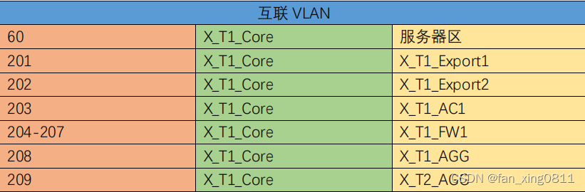
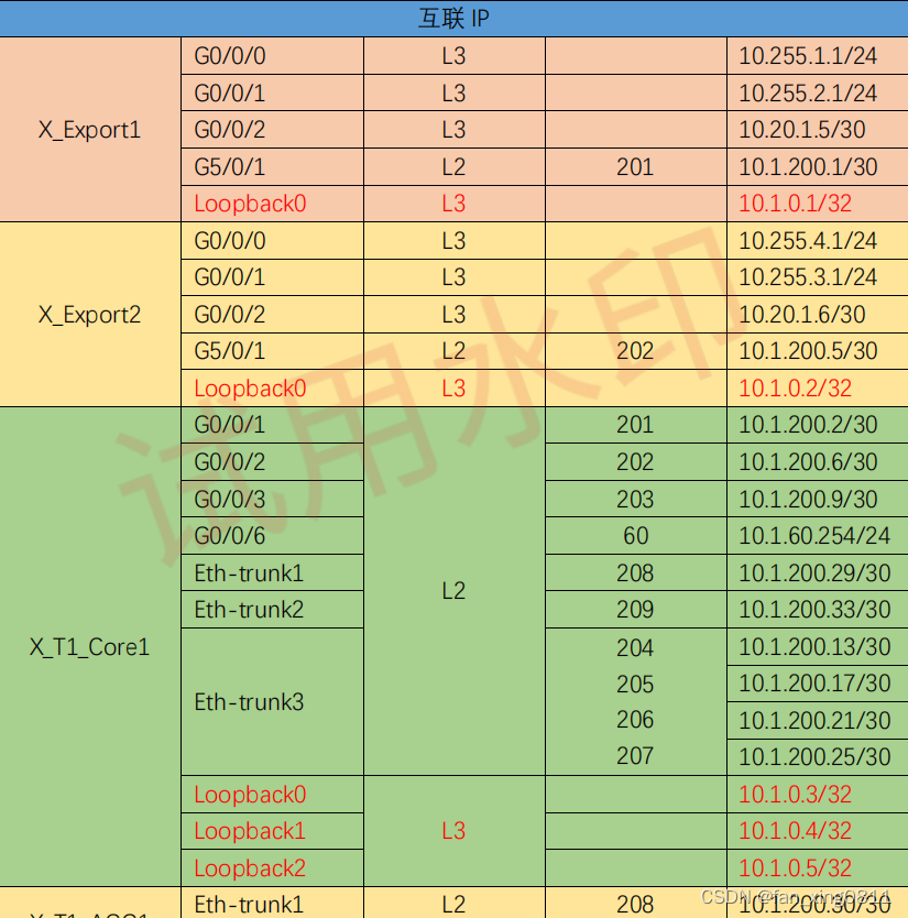
3.2.4 配置互联IP
3.2.4.1:配置Loopback口IP
1.X_T1_Export1
sy [X_Export1]interface LoopBack 0
[X_Export1-LoopBack0]ip address 10.1.0.1 32
2..X_T1_Export2
sy [X_Export2]interface LoopBack 0
[X_Export2-LoopBack0]ip address 10.1.0.2 32
3.X_T1_Core
sy [X_T1_Core1]interface LoopBack 0
[X_T1_Core1-LoopBack0]ip address 10.1.0.3 32
[X_T1_Core1]interface LoopBack 1
[X_T1_Core1-LoopBack1]ip binding vpn-instance Employee //因后续ospf要求,这里先将lo1和lo2分别绑定至内外部实例
[X_T1_Core1-LoopBack1]ip address 10.1.0.4 32
[X_T1_Core1]interface LoopBack 2
[X_T1_Core1-LoopBack1]ip binding vpn-instance Guest
[X_T1_Core1-LoopBack1]ip address 10.1.0.5 32
4.X_T1_AGG1
sy [X_T1_AGG1]interface LoopBack 0
[X_T1_AGG1-LoopBack0]ip address 10.1.0.6 32
5.X_T1_AGG2
sy [X_T1_AGG2]interface LoopBack 0
[X_T1_AGG2-LoopBack0]ip address 10.1.0.7 32
6.FW
sy [X_T1_FW1]interface LoopBack 0
[X_T1_FW1-LoopBack0]ip address 10.1.0.8 32
[X_T1_FW1]interface LoopBack 1
[X_T1_FW1-LoopBack1]ip address 10.1.0.9 32
7.AC
sy [X_T1_AC1]interface LoopBack 0
[X_T1_AC1-LoopBack0]ip address 10.1.0.11 32
3.2.4.2 Export与Core互联
A.在X_T1_Export1配置ip地址
sy [X_Export1]interface GigabitEthernet 5/0/1
[X_Export1-GigabitEthernet5/0/1]port link-type access
[X_Export1-GigabitEthernet5/0/1]port default vlan 201
[X_Export1]interface Vlanif 201
[X_Export1-Vlanif201]ip address 10.1.200.1 30
[X_Export1]interface GigabitEthernet 0/0/2
[X_Export1-GigabitEthernet0/0/2]ip address 10.20.1.5 30
B.在Core上配置去往Export1的地址
[X_T1_Core1]interface Vlanif 201
[X_T1_Core1-Vlanif201]ip address 10.1.200.2 30
[X_T1_Core1]interface GigabitEthernet 0/0/1
[X_T1_Core1-GigabitEthernet0/0/1]port link-type access
[X_T1_Core1-GigabitEthernet0/0/1]port default vlan 201
//Core与Export2,两台汇聚,AC的互联配置基本一样,对着表格写就可以,这里不做过多赘述。接下来我们重点说一下与防火墙和服务器的互联。
3.2.4.3 在Core上配置去往FW的链路及地址
sy [X_T1_Core1]interface Vlanif 204
[X_T1_Core1-Vlanif204]ip address 10.1.200.13 255.255.255.252
[X_T1_Core1]interface Vlanif 205
[X_T1_Core1-Vlanif205]ip address 10.1.200.17 255.255.255.252
[X_T1_Core1]interface Vlanif 206
[X_T1_Core1-Vlanif206]ip binding vpn-instance Employee
[X_T1_Core1-Vlanif206]ip address 10.1.200.21 255.255.255.252
[X_T1_Core1]interface Vlanif 207
[X_T1_Core1-Vlanif207]ip binding vpn-instance Guest
[X_T1_Core1-Vlanif207]ip address 10.1.200.25 255.255.255.252
//这里vlan206 vlan207需要跟防火墙两个虚拟系统对接,因此要绑定vpn实例。
3.2.4.4 FW上的配置
//在 FW 上创建 VLAN204-207,其中:
VLAN204,206 用于 Employee
VLAN205,207 用于 GuestA.在根墙上创建相应的接口
sy [X_T1_FW1]interface Vlanif 204
[X_T1_FW1]interface Vlanif 205
[X_T1_FW1]interface Vlanif 206
[X_T1_FW1]interface Vlanif 207
[X_T1_FW1]interface Loopback 0
[X_T1_FW1]interface Loopback 1
B.创建虚拟防火墙Employee,然后把vlan204,206分配给该防火墙,并配置安全区域与ip地址。
[X_T1_FW1]vsys enable
[X_T1_FW1]vsys name Employee
[X_T1_FW1-vsys-Employee]assign interface LoopBack 0
[X_T1_FW1-vsys-Employee]assign vlan 204
[X_T1_FW1-vsys-Employee]assign vlan 206
[X_T1_FW1]switch vsys Employee //进入虚拟防火墙视图
sy [X_T1_FW1-Employee]firewall zone trust
[X_T1_FW1-Employee-zone-trust]add interface Vlanif 206
[X_T1_FW1-Employee]firewall zone untrust
[X_T1_FW1-Employee-zone-untrust]add interface Vlanif 204
[X_T1_FW1-Employee-zone-untrust]add interface Virtual-if 1 //这个需求和ip在后面的需求会给出
[X_T1_FW1-Employee]interface Vlanif 204
[X_T1_FW1-Employee-Vlanif204]ip address 10.1.200.14 30
[X_T1_FW1-Employee-Vlanif204]service-manage ping permit
[X_T1_FW1-Employee]interface Vlanif 206
[X_T1_FW1-Employee-Vlanif206]ip address 10.1.200.22 30
[X_T1_FW1-Employee-Vlanif206]service-manage ping permit
[X_T1_FW1-Employee]interface LoopBack 0
[X_T1_FW1-Employee-LoopBack0]ip address 10.1.0.8 32
[X_T1_FW1-Employee]interface Virtual-if 1
[X_T1_FW1-Employee-Virtual-if1]ip address 10.1.200.253 32 //后续需求给出
// 虚拟防火墙Guest的配置与Employee类似,这里不再讲述
3.2.4.5 在Core上连接服务器区域网关地址
sy [X_T1_Core1]interface Vlanif 60
[X_T1_Core1-Vlanif60]ip binding vpn-instance Employee
[X_T1_Core1-Vlanif60]ip address 10.1.60.254 255.255.255.0
[X_T1_Core1]interface GigabitEthernet 0/0/6
[X_T1_Core1-GigabitEthernet0/0/6]port link-type access
[X_T1_Core1-GigabitEthernet0/0/6]port default vlan 60
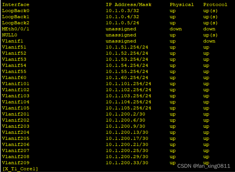
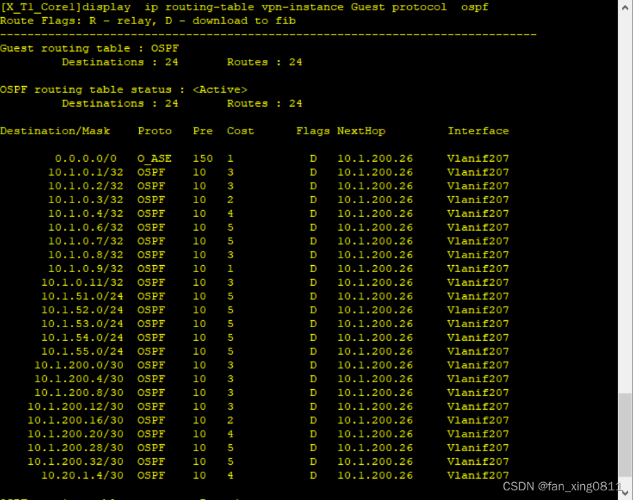
3.2.4.6 验证
在Core上输入display ip interface brief验证一下
3.3 OSPF
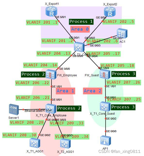
所有三层设备之间部署多区域 OSPF。 1. 两台出⼝路由器与核⼼交换机之间的链路属于⻣⼲⽹络,终端访问 Internet 流量由 出⼝两台路由器共同分担。 2. 核⼼交换机与 AC 之间的链路属于⻣⼲⽹格。 3. 根据⽹络隔离需求,将内部⽹络与访客⽹络分别划分到 OSPF 的区域 1 和区域 2。P.s.:因为有三种业务,公网,Employee,Guest,因此每个实例分别创建一个进程。
这里放一张逻辑拓扑图帮助大家更好的理解。
3.3.1 在X_T1_Core上配置OSPF
A.公网的OSPF进程:
[X_T1_Core1]ospf router-id 10.1.0.3
[X_T1_Core1-ospf-1]area 0
[X_T1_Core1-ospf-1-area-0.0.0.0]network 10.1.0.3 0.0.0.0
[X_T1_Core1-ospf-1-area-0.0.0.0]network 10.1.200.2 0.0.0.0 //去往export
[X_T1_Core1-ospf-1-area-0.0.0.0]network 10.1.200.6 0.0.0.0 //去往export
[X_T1_Core1-ospf-1-area-0.0.0.0]network 10.1.200.9 0.0.0.0 //去往AC
[X_T1_Core1-ospf-1]area 1
[X_T1_Core1-ospf-1-area-0.0.0.1]network 10.1.200.13 0.0.0.0 //连接FW的Employee
[X_T1_Core1-ospf-1]area 2
[X_T1_Core1-ospf-1-area-0.0.0.2]network 10.1.200.17 0.0.0.0 //连接FW的Guest
B.Employee的OSPF进程,宣告连接AGG,FW的网段及业务网段
//VLAN206 的 10.1.200.21 连接 FW 的 Employee。 //服务器网段宣告到 Employee。[X_T1_Core1]ospf 2 vpn-instance Employee router-id 10.1.0.4
[X_T1_Core1-ospf-2]vpn-instance-capability simple //用来禁止路由环路检测,直接进行路由计算,不输入这玩意会不通
[X_T1_Core1-ospf-2]area 1
[X_T1_Core1-ospf-2-area-0.0.0.1]network 10.1.0.4 0.0.0.0
[X_T1_Core1-ospf-2-area-0.0.0.1]network 10.1.51.254 0.0.0.0
[X_T1_Core1-ospf-2-area-0.0.0.1]network 10.1.52.254 0.0.0.0
[X_T1_Core1-ospf-2-area-0.0.0.1]network 10.1.53.254 0.0.0.0
[X_T1_Core1-ospf-2-area-0.0.0.1]network 10.1.54.254 0.0.0.0
[X_T1_Core1-ospf-2-area-0.0.0.1]network 10.1.55.254 0.0.0.0
[X_T1_Core1-ospf-2-area-0.0.0.1]network 10.1.60.254 0.0.0.0
[X_T1_Core1-ospf-2-area-0.0.0.1]network 10.1.200.21 0.0.0.0
[X_T1_Core1-ospf-2-area-0.0.0.1]network 10.1.200.29 0.0.0.0
[X_T1_Core1-ospf-2-area-0.0.0.1]network 10.1.200.33 0.0.0.0
C.Guest的OSPF进程
//VLAN207 的 10.1.200.25 连接虚拟墙 Guest[X_T1_Core1]ospf 3 vpn-instance Guest router-id 10.1.0.5
[X_T1_Core1-ospf-3]vpn-instance-capability simple
[X_T1_Core1-ospf-3]area 2
[X_T1_Core1-ospf-3-area-0.0.0.2]network 10.1.0.5 0.0.0.0
[X_T1_Core1-ospf-3-area-0.0.0.2]network 10.1.101.254 0.0.0.0
[X_T1_Core1-ospf-3-area-0.0.0.2]network 10.1.102.254 0.0.0.0
[X_T1_Core1-ospf-3-area-0.0.0.2]network 10.1.103.254 0.0.0.0
[X_T1_Core1-ospf-3-area-0.0.0.2]network 10.1.104.254 0.0.0.0
[X_T1_Core1-ospf-3-area-0.0.0.2]network 10.1.105.254 0.0.0.0
[X_T1_Core1-ospf-3-area-0.0.0.2]network 10.1.200.25 0.0.0.0
3.3.2 在X_T1_Export上配置OSPF
在X_T1_Export1配置OSPF:
sy [X_Export1]ospf 1 router-id 10.1.0.1
[X_Export1-ospf-1]default-route-advertise
[X_Export1-ospf-1]area 0
[X_Export1-ospf-1-area-0.0.0.0]network 10.1.0.1 0.0.0.0
[X_Export1-ospf-1-area-0.0.0.0]network 10.1.200.1 0.0.0.0
[X_Export1-ospf-1-area-0.0.0.0]network 10.20.1.5 0.0.0.0
//X_T1_Export2上的OSPF与在X_T1_Export1类似
3.3.3 在AC上配置OSPF
sy [X_T1_AC1]ospf router-id 10.1.0.11
[X_T1_AC1-ospf-1]area 0
[X_T1_AC1-ospf-1-area-0.0.0.0]network 10.1.0.11 0.0.0.0
[X_T1_AC1-ospf-1-area-0.0.0.0]network 10.1.200.10 0.0.0.0
3.3.4 在FW上配置OSPF
A.在FW根墙视图下配置虚拟墙的OSPF
sy [X_T1_FW1]ospf 2 vpn-instance Employee router-id 10.1.0.8
[X_T1_FW1-ospf-2]vpn-instance-capability simple
[X_T1_FW1-ospf-2]area 1
[X_T1_FW1-ospf-2-area-0.0.0.1]network 10.1.0.8 0.0.0.0
[X_T1_FW1-ospf-2-area-0.0.0.1]network 10.1.200.14 0.0.0.0
[X_T1_FW1-ospf-2-area-0.0.0.1]network 10.1.200.22 0.0.0.0
[X_T1_FW1]ospf 3 vpn-instance Guest router-id 10.1.0.9
[X_T1_FW1-ospf-3]vpn-instance-capability simple
[X_T1_FW1-ospf-3]area 2
[X_T1_FW1-ospf-3-area-0.0.0.2]network 10.1.0.9 0.0.0.0
[X_T1_FW1-ospf-3-area-0.0.0.2]network 10.1.200.18 0.0.0.0
[X_T1_FW1-ospf-3-area-0.0.0.2]network 10.1.200.26 0.0.0.0
B.允许OSPF的流量通过FW
现有环境无需配置以下策略也可以正常建立FULL邻居关系。但正常情况时需要配置。
[X_T1_FW1]switch vsys Employee
sy [X_T1_FW1-Employee]security-policy
[X_T1_FW1-Employee-policy-security]rule name permit_ospf
[X_T1_FW1-Employee-policy-security-rule-permit_ospf]source-zone trust
[X_T1_FW1-Employee-policy-security-rule-permit_ospf]source-zone untrust
[X_T1_FW1-Employee-policy-security-rule-permit_ospf]destination-zone local
[X_T1_FW1-Employee-policy-security-rule-permit_ospf]service protocol 89
[X_T1_FW1-Employee-policy-security-rule-permit_ospf]action permit
[X_T1_FW1]switch vsys Guest
sy [X_T1_FW1-Guest]security-policy
[X_T1_FW1-Guest-policy-security]rule name permit_ospf
[X_T1_FW1-Guest-policy-security-rule-permit_ospf]source-zone trust
[X_T1_FW1-Guest-policy-security-rule-permit_ospf]source-zone untrust
[X_T1_FW1-Guest-policy-security-rule-permit_ospf]destination-zone local
[X_T1_FW1-Guest-policy-security-rule-permit_ospf]service protocol 89
[X_T1_FW1-Guest-policy-security-rule-permit_ospf]action permit
3.3.5 在X_T1_AGG1上配置OSPF
sy [X_T1_AGG1]ospf 1 router-id 10.1.0.6
[X_T1_AGG1-ospf-1]area 1
[X_T1_AGG1-ospf-1-area-0.0.0.1]network 10.1.0.6 0.0.0.0
[X_T1_AGG1-ospf-1-area-0.0.0.1]network 10.1.200.30 0.0.0.0
[X_T1_AGG1-ospf-1-area-0.0.0.1]network 10.1.11.254 0.0.0.0
[X_T1_AGG1-ospf-1-area-0.0.0.1]network 10.1.12.254 0.0.0.0
[X_T1_AGG1-ospf-1-area-0.0.0.1]network 10.1.13.254 0.0.0.0
[X_T1_AGG1-ospf-1-area-0.0.0.1]network 10.1.14.254 0.0.0.0
[X_T1_AGG1-ospf-1-area-0.0.0.1]network 10.1.15.254 0.0.0.0
[X_T1_AGG1-ospf-1-area-0.0.0.1]network 10.1.21.254 0.0.0.0
[X_T1_AGG1-ospf-1-area-0.0.0.1]network 10.1.22.254 0.0.0.0
[X_T1_AGG1-ospf-1-area-0.0.0.1]network 10.1.23.254 0.0.0.0
[X_T1_AGG1-ospf-1-area-0.0.0.1]network 10.1.24.254 0.0.0.0
[X_T1_AGG1-ospf-1-area-0.0.0.1]network 10.1.25.254 0.0.0.0
//X_T2_AGG1的配置与在X_T1_AGG1类似
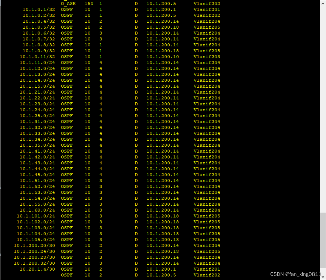
3.3.6 验证
在核心上分别输入display ospf peer brief和display ip routing-table protocol ospf验证配置

3.4 网络隔离
1. 在 X_T1_CORE1 上通过部署两个 VPN 实例实现内部、访客流量隔离。 1.1 实例名称为 Employee 与 Guest,RD 分别为 65001:1 和 65001:2; 1.2 表 1-1 中,外部⽆线⽤户属于 Guest,其它所有⽹络都属于 Employee。 2. 防⽕墙 X_T1_FW1,使⽤虚拟系统与 X_T1_CORE1 上的两个 VPN 实例 Guest 和 Employee 进⾏对接。 2.1 虚拟系统的名称与其对接的 VPN 实例名称保持⼀致; 2.2 VLAN204,VLAN206 属于实例 Employee, VLAN204 划分进安全区域 Untrust, VLAN206 划分进安全区域 Trust; 2.3 VLAN205,VLAN207 属于实例 Guest;VLAN205 划分进安全区域 Untrust, VLAN207 划分进安全区域 Trust。 2.4 虚拟系统 Employee 与虚拟系统 Guest 和 X_TI_CORE1 之间的链路分别属于 OSPF 的区域 1 和区域 2。 2.5 使⽤ IP-Prefix 作为过滤器进⾏路由过滤,Employee 与 Guest 之间不学习对⽅ 终所在⽹段的明细路由与对应的 3 类 LSA。 2.6 在不使⽤策略路由的前提下,跨 OSPF 区域的流量必须经过防⽕墙。 部分需求已在前面做过,例如划分实例设置RD值,防火墙虚拟系统与实例对接等。在做剩下的需求之前,先来复习一下3类LSA的概念:
3类LSA由ABR产生,描述区域间的路由信息。
3.4.1 阻断Employee与Guest之间的流量
在Core上配置前缀列表,然后基于OSPF区域配置3类LSA过滤
sy [X_T1_Core1]ip ip-prefix deny_Guest deny 10.1.101.0 24
[X_T1_Core1]ip ip-prefix deny_Guest deny 10.1.102.0 24
[X_T1_Core1]ip ip-prefix deny_Guest deny 10.1.103.0 24
[X_T1_Core1]ip ip-prefix deny_Guest deny 10.1.104.0 24
[X_T1_Core1]ip ip-prefix deny_Guest deny 10.1.105.0 24
[X_T1_Core1]ip ip-prefix deny_Guest permit 0.0.0.0 0 less-equal 32
[X_T1_Core1]ospf 1
[X_T1_Core1-ospf-1]area 1[X_T1_Core1-ospf-1-area-0.0.0.1]filter ip-prefix deny_Guest import
[X_T1_Core1]ip ip-prefix deny_Employee deny 10.1.11.0 24
[X_T1_Core1]ip ip-prefix deny_Employee deny 10.1.12.0 24
[X_T1_Core1]ip ip-prefix deny_Employee deny 10.1.13.0 24
[X_T1_Core1]ip ip-prefix deny_Employee deny 10.1.14.0 24
[X_T1_Core1]ip ip-prefix deny_Employee deny 10.1.15.0 24
[X_T1_Core1]ip ip-prefix deny_Employee deny 10.1.21.0 24
[X_T1_Core1]ip ip-prefix deny_Employee deny 10.1.22.0 24
[X_T1_Core1]ip ip-prefix deny_Employee deny 10.1.23.0 24
[X_T1_Core1]ip ip-prefix deny_Employee deny 10.1.24.0 24
[X_T1_Core1]ip ip-prefix deny_Employee deny 10.1.25.0 24
[X_T1_Core1]ip ip-prefix deny_Employee deny 10.1.31.0 24
[X_T1_Core1]ip ip-prefix deny_Employee deny 10.1.32.0 24
[X_T1_Core1]ip ip-prefix deny_Employee deny 10.1.33.0 24
[X_T1_Core1]ip ip-prefix deny_Employee deny 10.1.34.0 24
[X_T1_Core1]ip ip-prefix deny_Employee deny 10.1.35.0 24
[X_T1_Core1]ip ip-prefix deny_Employee deny 10.1.41.0 24
[X_T1_Core1]ip ip-prefix deny_Employee deny 10.1.42.0 24
[X_T1_Core1]ip ip-prefix deny_Employee deny 10.1.43.0 24
[X_T1_Core1]ip ip-prefix deny_Employee deny 10.1.44.0 24
[X_T1_Core1]ip ip-prefix deny_Employee deny 10.1.45.0 24
[X_T1_Core1]ip ip-prefix deny_Employee deny 10.1.51.0 24
[X_T1_Core1]ip ip-prefix deny_Employee deny 10.1.52.0 24
[X_T1_Core1]ip ip-prefix deny_Employee deny 10.1.53.0 24
[X_T1_Core1]ip ip-prefix deny_Employee deny 10.1.54.0 24
[X_T1_Core1]ip ip-prefix deny_Employee deny 10.1.55.0 24
[X_T1_Core1]ip ip-prefix deny_Employee deny 10.1.60.0 24
[X_T1_Core1]ip ip-prefix deny_Employee permit 0.0.0.0 0 less-equal 32
[X_T1_Core1]ospf 1
[X_T1_Core1-ospf-1]area 2[X_T1_Core1-ospf-1-area-0.0.0.2]filter ip-prefix deny_Employee import
3.4.2 验证
3.5 WLAN扩容需求
1. X_T1_AP1 已在 AC 上线且正常提供无线服务,X_T2_AP1 和 X_T1_AP1 在共同管理 VLAN 上线并提供相同的无线服务,即延续当前的 WLAN 相关配置: 1.1 内部无线用户使用的 SSID 为 X_Employee_010,密码为 Huawei@123 1.2 外部无线用户使用的 SSID 为 X_Guest_010,密码为 Huawei@123 1.3 ⽆线⽤户数据采⽤集中转发的机制,统⼀由 AC 进⾏数据转发 2. 当前网络分别为内部与外部无线用户预留 10.1.51.0/24(vlan51)与 10.1.101.0/24 (vlan101),经常出现 由于 DHCP 服务器地址不足导致用户无法正常接入无线网络的 情况。现需要根据表 1-1 扩充可用地址数量。同时还需尽量保证同一用户接入网络时, IP 地址不发送改变。//这里说到了⽆线⽤户数据采⽤集中转发的机制,统⼀由 AC 进⾏数据转发,这就是为什么前面核心和汇聚上需要透传这个管理vlan100
3.5.1 AP上线配置
A.开启dhcp服务,为AP分配IP地址。
sy [X_T1_AC1]dhcp enable
[X_T1_AC1]interface Vlanif 100
[X_T1_AC1-Vlanif100]ip address 10.1.100.254 24
[X_T1_AC1-Vlanif100]dhcp select interface //这里dhcp选用接口模式
B.在X_T1_ACC1和X_T2_ACC2上允许配置AP属于的管理VLAN
interface GigabitEthernet0/0/22 port link-type access port default vlan 100
C.配置AC与AP之间通信的IP地址
[X_T1_AC1]capwap source interface Vlanif 203 //采用capwap隧道模式
D.根据MAC地址注册AP
先在ap上查询mac地址
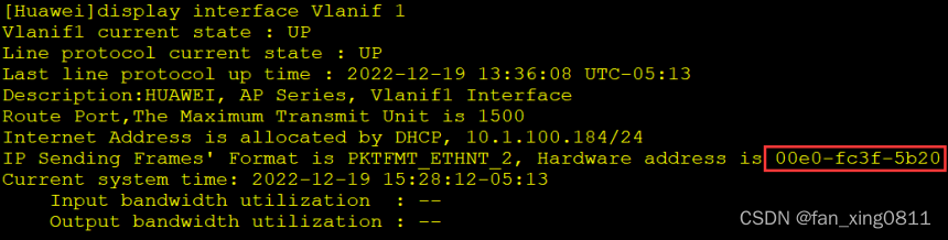
[X_T1_AC1]wlan
[X_T1_AC1-wlan-view]ap-id 0 ap-mac 00e0-fc3f-5b20
[X_T1_AC1-wlan-view]ap-name X_T1_AP1
[X_T1_AC1-wlan-ap-0]ap-group default //暂时划入缺省组
[X_T1_AC1-wlan-view]ap-id 1 ap-mac 00e0-fc9a-1d80
[X_T1_AC1-wlan-view]ap-name X_T2_AP2
[X_T1_AC1-wlan-ap-1]ap-group default
3.5.2 配置wlan配置模板
A.配置VLAN pool
[X_T1_AC1]vlan pool Employee
[X_T1_AC1-vlan-pool-Employee]vlan 51 to 55
[X_T1_AC1]vlan pool Guest
[X_T1_AC1-vlan-pool-Guest]vlan 101 to 105
B.配置SSID模板
[X_T1_AC1]wlan
[X_T1_AC1-wlan-view]ssid-profile name Employee
[X_T1_AC1-wlan-ssid-prof-Employee]ssid X_Employee_010
[X_T1_AC1-wlan-view]ssid-profile name Guest
[X_T1_AC1-wlan-ssid-prof-Guest]ssid X_Guest_010
C.配置安全模板
[X_T1_AC1-wlan-view]security-profile name Employee
[X_T1_AC1-wlan-sec-prof-Employee]security wpa-wpa2 psk pass-phrase Huawei@123 ae
s[X_T1_AC1-wlan-view]security-profile name Guest
[X_T1_AC1-wlan-sec-prof-Guest]security wpa-wpa2 psk pass-phrase Huawei@123 aes
D.配置vap模板,关联以上参数
[X_T1_AC1-wlan-view]vap-profile name X_Employee_010
[X_T1_AC1-wlan-vap-prof-X_Employee_010]forward-mode tunnel //设置转发模式为隧道模式
[X_T1_AC1-wlan-vap-prof-X_Employee_010]service-vlan vlan-pool Employee
[X_T1_AC1-wlan-vap-prof-X_Employee_010]ssid-profile Employee
[X_T1_AC1-wlan-vap-prof-X_Employee_010]security-profile Employee
[X_T1_AC1-wlan-view]vap-profile name X_Guest_010
[X_T1_AC1-wlan-vap-prof-X_Guest_010]forward-mode tunnel
[X_T1_AC1-wlan-vap-prof-X_Guest_010]service-vlan vlan-pool Guest
[X_T1_AC1-wlan-vap-prof-X_Guest_010]ssid-profile Guest
[X_T1_AC1-wlan-vap-prof-X_Guest_010]security-profile Guest
3.5.3将VAP模板关联到AP组,并发送射频
[X_T1_AC1-wlan-view]ap-group name Employee
[X_T1_AC1-wlan-ap-group-Employee]vap-profile X_Employee_010 wlan 1 radio all
[X_T1_AC1-wlan-ap-group-Employee]vap-profile X_Guest_010 wlan 2 radio all
[X_T1_AC1-wlan-view]ap-group name Guest
[X_T1_AC1-wlan-ap-group-Guest]vap-profile X_Employee_010 wlan 1 radio all
[X_T1_AC1-wlan-ap-group-Guest]vap-profile X_Guest_010 wlan 2 radio all
3.5.4 AP关联到AP组
[X_T1_AC1-wlan-view]ap-id 0
[X_T1_AC1-wlan-ap-0]ap-group Employee
[X_T1_AC1-wlan-view]ap-id 1
[X_T1_AC1-wlan-ap-1]ap-group Guest
3.5.5 验证
配置完成后AP会显示信号覆盖范围
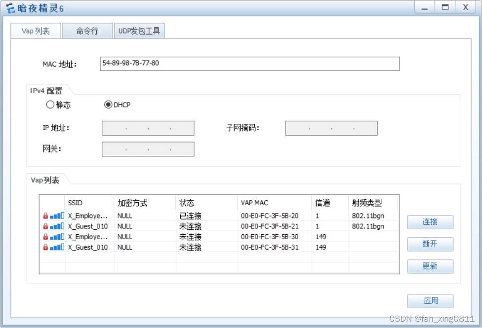
能通过dhcp成功获取地址信息
//这里可以顺便验证一下有线的终端dhcp配置是否正确
3.6 出口网络
1. 新增出口路由器 X_T1_Export2,采用双 Internet 线路实现上网流量的负载分担。 1.1 GE0/0/9 采用静态配置 IP 地址:10.255.3.1/24,网关为 10.255.3.254 1.2 GE0/0/10 采用静态配置 IP 地址:10.255.4.1/24,网关为 10.255.4.254 2. 所有用户通过 X_T1_Export2 路由器访问 Internet 时,需要通过 NAT 替换私网 IP 地址 2.1 对所有通过防火墙策略的 IP 报文进行源地址与端口转换; 2.2 Export2 的 GE0/0/9 使用当前接口地址作为转换后的地址; 2.3 Export2 的 GE0/0/10 使用地址池(10.255.4.2 - 10.255.4.100)替换私网 IP 地 址和端口; 2.4 X 园区内网服务器(10.1.60.101)向外提供 WEB 服务(端口号为 80),公网用户 通过 10.255.4.1 的 8081 号端口访问该服务器。3.6.1 在X_T1_Export2上
[X_Export2]ip route-static 0.0.0.0 0 10.255.3.254
[X_Export2]ip route-static 0.0.0.0 0 10.255.4.254 //两条等价路由
[X_Export2]acl 2000
[X_Export2-acl-basic-2000]rule permit
[X_Export2]nat address-group 1 10.255.4.2 10.255.4.100
[X_Export2]interface GigabitEthernet 0/0/0
[X_Export2-GigabitEthernet0/0/0]ip address 10.255.3.1 24
[X_Export2-GigabitEthernet0/0/0]nat outbound 2000 //去往ISP1的接口
[X_Export2]interface GigabitEthernet 0/0/1
[X_Export2-GigabitEthernet0/0/1]ip address 10.255.3.1 24
[X_Export2-GigabitEthernet0/0/1]nat outbound 2000 //去往ISP2的接口
// 在Export1上的配置与Export2类似
3.7 网络安全
1. 防火墙上配置安全策略实现用户访问权限的控制 1.1 仅采购部(11-15),市场部(21-25),内部无线用户(51-55),外部无线用户(101- 105)可以访问 Internet; 1.2 内部无线用户仅可以访问服务器网段的某一服务器,IP 为 10.1.60.100; 1.3 外部无线用户仅可以访问服务器网段中的 HTTP 服务(名为 Guest_Service),IP 为 10.1.60.99,端口为 3389(TCP)。 2. 安全策略需按照下列规则配置: 2.1 必须包含源、目的安全区域 2.2 若包含特定服务,需使用系统预定义服务或自定义服务(service-set)表示 3. 外部无线用户访问 Guest_Service 服务的流量需要直接在 Guest 和 Employee 两个虚 拟系统之间转发。 3.1 Guest 和 Employee 两个虚拟系统的 Virtual-if 属于 untrust 安全区域,IP 地址分 别为 10.1.200.254/32 和 10.1.200.253/32; 3.2 仅当外部无线用户访问 10.1.60.99 时,流量直接在虚拟系统之间转发。3.7.1 配置静态路由实现虚拟系统直接转发
在根墙上配置虚拟 FW 之间的静态路由,实现跨实例业务直接互访(去和返回的流量)。sy [X_T1_FW1]ip route-static vpn-instance Guest 10.1.60.99 32 vpn-instance Employee
[X_T1_FW1]ip route-static vpn-instance Employee 10.1.101.0 24 vpn-instance Guest [X_T1_FW1]ip route-static vpn-instance Employee 10.1.102.0 24 vpn-instance Guest [X_T1_FW1]ip route-static vpn-instance Employee 10.1.103.0 24 vpn-instance Guest [X_T1_FW1]ip route-static vpn-instance Employee 10.1.104.0 24 vpn-instance Guest [X_T1_FW1]ip route-static vpn-instance Employee 10.1.105.0 24 vpn-instance Guest
3.7.2 控制Guest的流量
A.在Guest虚拟FW上,配置对应的IP地址集和基本服务集,用于安全策略调用[X_T1_FW1]switch vsys GuestB.在Guest虚拟FW上,根据题目需求配置安全策略sy [X_T1_FW1-Guest]ip address-set Guest type object [X_T1_FW1-Guest-object-address-set-Guest]address 10.1.101.0 mask 24 [X_T1_FW1-Guest-object-address-set-Guest]address 10.1.102.0 mask 24 [X_T1_FW1-Guest-object-address-set-Guest]address 10.1.103.0 mask 24 [X_T1_FW1-Guest-object-address-set-Guest]address 10.1.104.0 mask 24 [X_T1_FW1-Guest-object-address-set-Guest]address 10.1.105.0 mask 24 [X_T1_FW1-Guest]ip service-set Guest_Service type object [X_T1_FW1-Guest-object-service-set-Guest_Service]service protocol tcp destinati
on-port 3389
[X_T1_FW1-Guest]security-policy [X_T1_FW1-Guest-policy-security]rule name Guest_Service [X_T1_FW1-Guest-policy-security-rule-Guest_Service]source-zone trust [X_T1_FW1-Guest-policy-security-rule-Guest_Service]destination-zone untrust [X_T1_FW1-Guest-policy-security-rule-Guest_Service]source-address address-set Gu//Employe虚拟FW上的配置与Guest类似,这里不再重复
est [X_T1_FW1-Guest-policy-security-rule-Guest_Service]destination-address 10.1.60.9
9 32 [X_T1_FW1-Guest-policy-security-rule-Guest_Service]service Guest_Service [X_T1_FW1-Guest-policy-security-rule-Guest_Service]action permit
[X_T1_FW1-Guest-policy-security]rule name deny_other
[X_T1_FW1-Guest-policy-security-rule-deny_other]source-zone trust
[X_T1_FW1-Guest-policy-security-rule-deny_other]destination-zone untrust
[X_T1_FW1-Guest-policy-security-rule-deny_other]source-address address-set Guest
[X_T1_FW1-Guest-policy-security-rule-deny_other]destination-address 10.1.60.0 24
[X_T1_FW1-Guest-policy-security-rule-deny_other]action deny
[X_T1_FW1-Guest-policy-security]rule name internet
[X_T1_FW1-Guest-policy-security-rule-internet]source-zone trust
[X_T1_FW1-Guest-policy-security-rule-internet]destination-zone untrust
[X_T1_FW1-Guest-policy-security-rule-internet]source-address address-set Guest
[X_T1_FW1-Guest-policy-security-rule-internet]action permit
3.8 引导流量转发(路由重定向)
3.8.1.traffic-redirect重定向
由于内部无线业务属于 Employee 实例,服务器区也属于 Employee 实例,同实例之
间的流量无法被路由引导到 FW 上,所以需要在内部无线网关的 VLANIF 下,配置
traffic-redirect 重定向流量到 FW。
在Core上:[X_T1_Core1]acl 3000 [X_T1_Core1-acl-adv-3000]rule 5 permit ip source 10.1.51.0 0.0.0.255 destination
10.1.60.0 0.0.0.255 [X_T1_Core1-acl-adv-3000]rule 10 permit ip source 10.1.52.0 0.0.0.255 destination
10.1.60.0 0.0.0.255 [X_T1_Core1-acl-adv-3000]rule 15 permit ip source 10.1.53.0 0.0.0.255 destination
10.1.60.0 0.0.0.255 [X_T1_Core1-acl-adv-3000]rule 20 permit ip source 10.1.54.0 0.0.0.255 destination
10.1.60.0 0.0.0.255 [X_T1_Core1-acl-adv-3000]rule 25 permit ip source 10.1.55.0 0.0.0.255 destination
10.1.60.0 0.0.0.255
[X_T1_Core1]interface GigabitEthernet 0/0/3
[X_T1_Core1-GigabitEthernet0/0/3]traffic-redirect inbound acl 3000 ip-nexthop 10
.1.200.22 //模拟器不支持在 SVI 口配置,因此只能在物理接口下配置。请注意:必须在入接口上配置,否则策略不生效
3.8.2 PBR
内网 WEB 服务器通过 Core1 的 public 路由表回包给外网用户,需要通过 PBR 把 回包流量送到 X_Export2,否则就可能通过等价的缺省路由发送到 X_Export1,导致 业务不通。[X_T1_Core1]acl 3001 [X_T1_Core1-acl-adv-3001]rule permit ip source 10.1.60.101 0//至于为什么在Eth-trunk3上配置而不是G0/0/6?因为服务器的流量要先经过防火墙,再从Eth-trunk3进入,然后才经过重定向转发出去。 在X_Export2上执行基于MQC的PBR,让web服务器回包通过NAT server的接口转发。
[X_T1_Core1]interface Eth-Trunk 3
[X_T1_Core1-Eth-Trunk3]traffic-redirect inbound acl 3001 ip-nexthop 10.1.200.5 //这里同理,只能在物理接口上配置。
[X_Export2]acl 3001 [X_Export2-acl-adv-3001]rule permit ip source 10.1.60.101 0 [X_Export2]traffic classifier web [X_Export2-classifier-web]if-match acl 3001 [X_Export2]traffic behavior web [X_Export2-behavior-web]redirect ip-nexthop 10.255.4.254 [X_Export2]traffic policy web [X_Export2-trafficpolicy-web]classifier web behavior web
[X_Export2]interface Vlanif 202
[X_Export2-Vlanif202]traffic-policy web inbound
4.结语
至此,全部配置完毕,所有需求均已满足。希望我的个人理解和配置能够帮助到大家, 也祝各位备考IP、IE的朋友们一把过,拿高分!本文来自互联网用户投稿,文章观点仅代表作者本人,不代表本站立场,不承担相关法律责任。如若转载,请注明出处。 如若内容造成侵权/违法违规/事实不符,请点击【内容举报】进行投诉反馈!