halcon显示坐标_手眼标定相机固定halcon示例
* 静态相机的手眼标定,适用于scara机器人* Provide the description file of the calibration plate and the* camera parameters of the previously calibrated camera* 提供标定板的描述文件和先前已经标定过的相机参数CalibObjDescr := 'calibrate_hand_eye_scara_setup_01_calplate.cpd'* 标定板的厚度,单位mCalibrationPlateThickness := 0.003* [Focus, Kappa, Sx, Sy, Cx, Cy, ImageWidth, ImageHeight]CameraParam := [0.0165251,-642.277,4.65521e-006,4.65e-006,595.817,521.75,1280,1024]* * Set the thickness of the objects to be grasped to be able to* define the pose of the measurement plane correctly* 被抓取物体的厚度, 方便后面确定测量平面的姿势ObjectThickness := 0.001* dev_close_window ()dev_open_window_fit_size (0, 0, 1280, 1024, 640, -1, WindowHandle)set_display_font (WindowHandle, 14, 'mono', 'true', 'false')dev_update_off ()* * 1. Acquire calibration images and corresponding robot poses* 1. 获取校准图象和对应的机器人位姿* * Create a new calibration model* 创建一个halcon的标定数据模型,设置的标定类类型为hand_eye_scara_stationary_cam,包括一个相机一个标定对象* 得到数据模型的句柄create_calib_data ('hand_eye_scara_stationary_cam', 1, 1, CalibDataID)* Set the camera parameters in the calibration model* 设置标定数据模型的参数,此处设置的参数是area_scan_division相机类型的相机参数,set_calib_data_cam_param (CalibDataID, 0, 'area_scan_division', CameraParam)* Set the calibration plate in the calibration model* 在标定数据模型中的定义标定对象set_calib_data_calib_object (CalibDataID, 0, CalibObjDescr)for Index := 1 to 10 by 1 * Read the calibration image * 读标定图像, read_image (CalibImage, '3d_machine_vision/handeye/scara_stationary_cam_setup_01_calib_' + Index$'02') * Read the corresponding robot pose (pose of the tool in the * robot base coordinate system) * 读取标定板在该标定位置的时候,机器人工具末端在机器人基坐标系的位姿 read_pose ('scara_stationary_cam_setup_01_tool_in_base_pose_' + Index$'02' + '.dat', ToolInBasePose) * Set the robot pose in the calibration model * 设置机器人末端位姿到标定模型中 set_calib_data (CalibDataID, 'tool', Index, 'tool_in_base_pose', ToolInBasePose) * Determine the pose of the calibration plate in the camera * coordinate system and set the pose in the calibration model * 得到标定板在相机坐标系下的位姿,并且将该位姿设置到标定模型中 find_calib_object (CalibImage, CalibDataID, 0, 0, Index, [], []) * Visualize dev_display (CalibImage) * 从标定模型中得到标定对象在相机坐标中的位姿 get_calib_data_observ_pose (CalibDataID, 0, 0, Index, ObjInCameraPose) * 可视化校定板的3D模型,同时在标定板板面上显示xy坐标轴 disp_caltab (WindowHandle, CalibObjDescr, CameraParam, ObjInCameraPose, 1) disp_message (WindowHandle, 'Calibration image ' + Index + ' of 10', 'window', 12, 12, 'black', 'true') wait_seconds (0.2)endfordisp_continue_message (WindowHandle, 'black', 'true')stop ()* * 2. Perform the hand-eye calibration* 执行手眼标定,得到标定结果(机器人基坐标系在相机坐标系中的表示)* calibrate_hand_eye (CalibDataID, Errors)* Get the result of the calibration, i.e., the pose of* the robot base in the camera coordinate system* 获取标定结果,机器人基坐标系在相机坐标系中的表示get_calib_data (CalibDataID, 'camera', 0, 'base_in_cam_pose', BaseInCamPosePre)* Free the calibration model* 释放标定数据模型clear_calib_data (CalibDataID)* Visualize* 显示标定结果的位姿disp_preliminary_result (WindowHandle, BaseInCamPosePre, Errors)disp_continue_message (WindowHandle, 'black', 'true')stop ()* * 3. Fix the pose ambiguity* 确定估计位姿* * 读参考对象图象read_image (ImageRef, '3d_machine_vision/handeye/scara_stationary_cam_setup_01_calib_ref')* 获取参考校正对象在相机坐标系中表示的位姿get_calib_plate_pose (ImageRef, CameraParam, CalibObjDescr, ObjInCamPoseRef)* 读取机器人工具末端移动到参考标定板中心后机器人工具末端在机器人基坐标系中表示的位姿read_pose ('scara_stationary_cam_setup_01_tool_in_base_pose_ref.dat', ToolInBasePoseRef)* 由此确定标定板底面中心的位姿在相机坐标系中表示的位姿,以及ToolInBasePoseRef位姿和BaseInCamPosePre位姿之间的Z轴差fix_scara_ambiguity_stationary_cam (BaseInCamPosePre, ToolInBasePoseRef, ObjInCamPoseRef, ZCorrection)* 获得标定板底面中心的位姿在相机坐标系中的表示set_origin_pose (BaseInCamPosePre, 0, 0, ZCorrection, BaseInCamPose)* * Visualizedisp_final_results (WindowHandle, BaseInCamPosePre, BaseInCamPose)disp_end_of_program_message (WindowHandle, 'black', 'true')* * After the hand-eye calibration is performed, the resulting pose* BaseInCamPose can be used in robotic grasping applications:* Let us assume that the camera acquires an image of the object that* should be grasped. From the image, the pose of the object in the* camera coordinate system must be determined (-> ObjInCamPose) by* using image processing.* Based on this pose and the result of the calibration* (BaseInCamPose), the robot pose can be computed that is necessary* to grasp the object (-> ObjInBasePose):* 将机器人基坐标系位姿在相机坐标系中的表示,反转为相机坐标系中的位姿在机器人基坐标系中的表示pose_invert (BaseInCamPose, CamInBasePose)* 对象在相机坐标系的位姿ObjInCamPose := [0.0035,-0.0128,0.7981,1.345,356.158,180.194,0]* 对象在机器人坐标系中的位姿pose_compose (CamInBasePose, ObjInCamPose, ObjInBasePose)* * 4. Prepare additional data required for the pose estimation of the* objects to be grasped* 准备被抓取物体位姿估计的其他数据* * * Determine the pose of the measurement plane* 确定测量平面在相机坐标系的位姿set_origin_pose (ObjInCamPoseRef, 0, 0, CalibrationPlateThickness - ObjectThickness, MPInCamPose)* * 5. Write the results for using them in a pick-and-place application* - Results of hand-eye calibration* 保存结果方便在后续的应用程序中使用* 手眼标定的结果保存write_pose (CamInBasePose, 'cam_in_base_pose.dat')* - Data required for pose estimation of the objects to be grasped* from the original image* 相机参数的保存write_cam_par (CameraParam, 'camera_parameters.dat')* 测量平面在相机坐标系中的位姿的保存write_pose (MPInCamPose, 'measurement_plane_in_cam_pose.dat')get_calib_plate_pose函数体的内容如下:
create_calib_data ('calibration_object', 1, 1, CalibDataID)set_calib_data_cam_param (CalibDataID, 0, 'area_scan_division', CameraParam)set_calib_data_calib_object (CalibDataID, 0, CalibObjDescr)find_calib_object (Image, CalibDataID, 0, 0, 0, [], [])* 获取被校正对象的姿态,相对于相机坐标系get_calib_data_observ_pose (CalibDataID, 0, 0, 0, Pose)clear_calib_data (CalibDataID)return ()fix_scara_ambiguity_stationary_cam函数体的内容如下:
* 对位姿矩阵求逆,反转相对坐标系,之前是机器人基座标系相对于相机坐标系,* 通过该算子,变成相机坐标系相对于机器人基坐标系pose_invert (BaseInCamPosePre, CamInBasePose)* 两个位姿矩阵乘,得到标定板中心相对于机器人基坐标系的位姿* 具体理论过程,参看下式以及Miuplay微信公众号文章* Stationary camera: H(cam* | | |* CameraPose RobotPoses CalibrationPosepose_compose (CamInBasePose, ObjInCamPose, ObjInBasePose)* 得到Z的差值ZCorrection := ObjInBasePose[2] - ToolInBasePose[2]return ()重点说明:
1. 整个标定的代码,明确说明了是适用于scara机器人。scara机器人是XY平面运动的机器人,当然,它也能在Z轴方向上运动。只是scara机器人的末端无法翻转。
2. 在for循环中,循环次数是10,循环体中操作是读不同位姿的标定板图像,然后读机器人工具末端位姿,从标定数据模型中得到每次标定对象在相机坐标系中的位姿。
3. 手眼标定的算子是calibrate_hand_eye ,这是halcon12,halcon10中是hand_eye_calibration。
4. 手眼标定之后,使用算子get_calib_data获取手眼标定结果。
5. 一定要记得使用算子clear_calib_data 释放标定数据模型。
6. 单相机标定,是无法确定Z轴的坐标的,因此,需要一个步骤来确定Z轴的坐标,因为是scara机器人,在一个确定的平面上,Z的值是确定。通过机器人工具坐标和某对象的坐标,这俩坐标都是在相机坐标系中表示的,做差,即可得到手眼标定中Z轴的坐标。
7. 因为标定板和待抓取物体都是有厚度的,在确定具体的对象在机器人基坐标系总的抓取坐标时,需要将他们的厚度考虑进去,并且为了简化后续的抓取坐标的计算,需要将一些手眼标定的结果保存起来。因此,将厚度考虑进去之后,得到测量平面相对于相机坐标系的位姿,保存该位姿,同时需要保存的还有相机参数,机器人基坐标系相对于相机坐标系的位姿。
执行流程和结果:
for循环中的执行效果,读取的标定板图像:

for循环中的执行效果,显示标定效果:

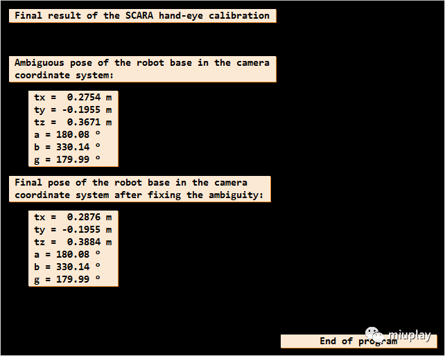
手眼标定后的结果显示,base_H_cam:

不关注Z轴情况下机器人基坐标系在相机坐标系中的位姿,和将Z轴值加入后机器人基坐标系在相机坐标系中的位姿:
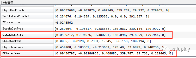
方便后续进行机器人抓取位姿计算而被保存的值:
-----------------------
-----------------------
不煮鸡汤,不制造焦虑,不宣扬速成。技术都是脚踏实地,功到渠成。
妙玩科技
公众号ID:miuplay
个人微信号:Miuplay
交流QQ群:940437523
本文来自互联网用户投稿,文章观点仅代表作者本人,不代表本站立场,不承担相关法律责任。如若转载,请注明出处。 如若内容造成侵权/违法违规/事实不符,请点击【内容举报】进行投诉反馈!