MYIR-ZYNQ7000系列-zturn教程(22):用axi_iic对24C32进行读写
开发板环境:vivado 2017.4 ,开发板型号xc7z020clg400-1,这个工程主要用axi_iic对24C32进行读写
链接:https://pan.baidu.com/s/1OHeFNlLTzk2xsaOUdUZ0kw 提取码:xfwa
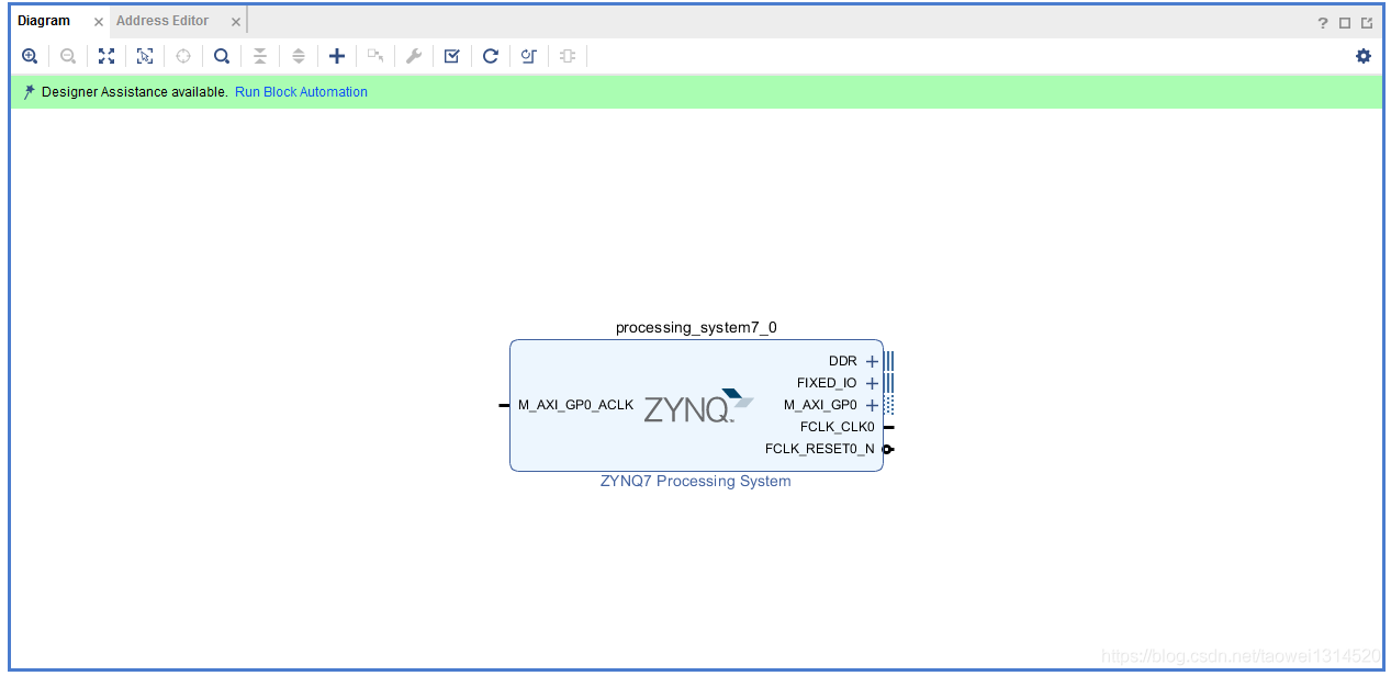
Step1 新建工程,调用一个zynq核并配置
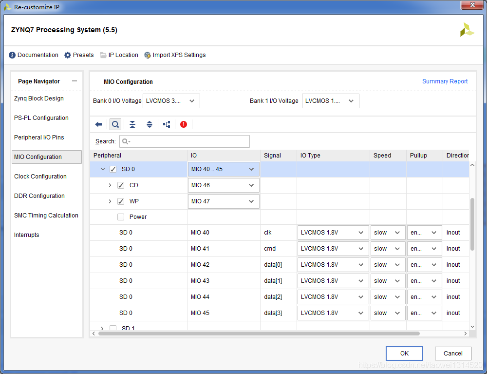
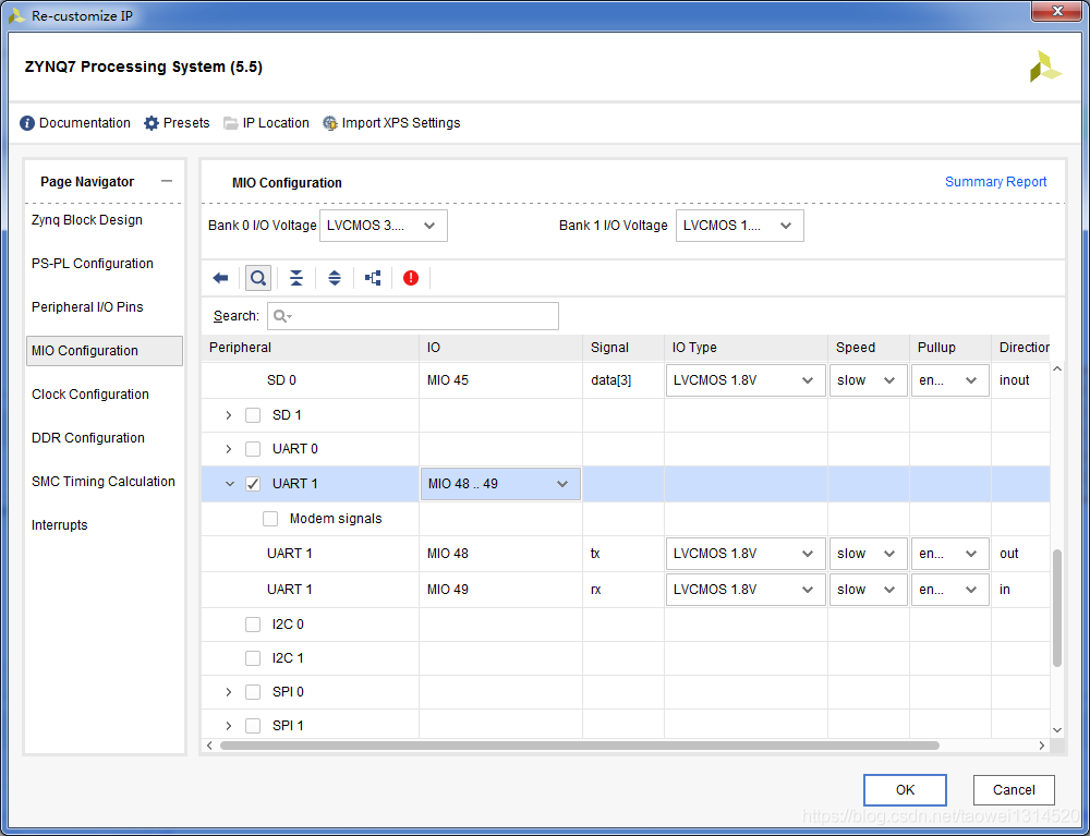
设置SD卡管脚和uart(不同的开发板会有所差异)
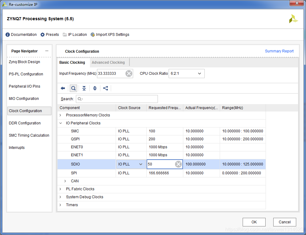
设置SDIO频率为50M
设置DDR型号(不同的开发板会有所不同)
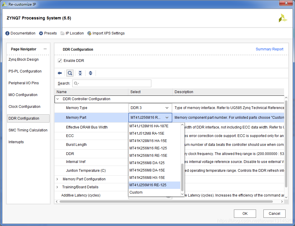
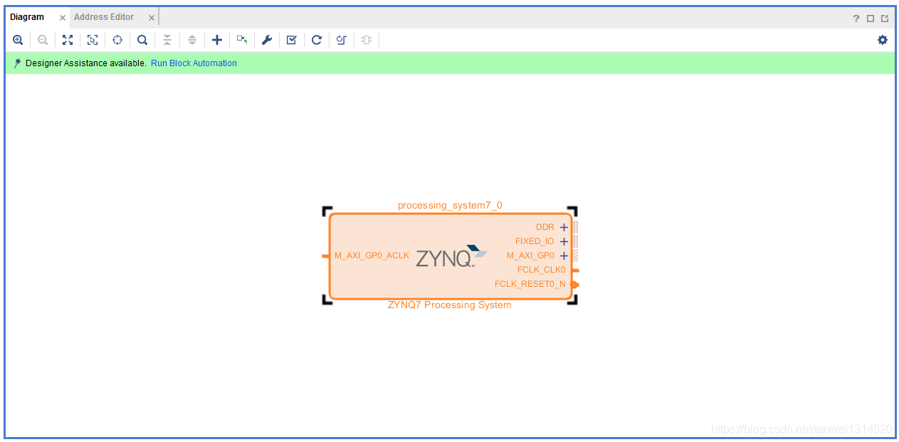
配置完成后,如下图所示
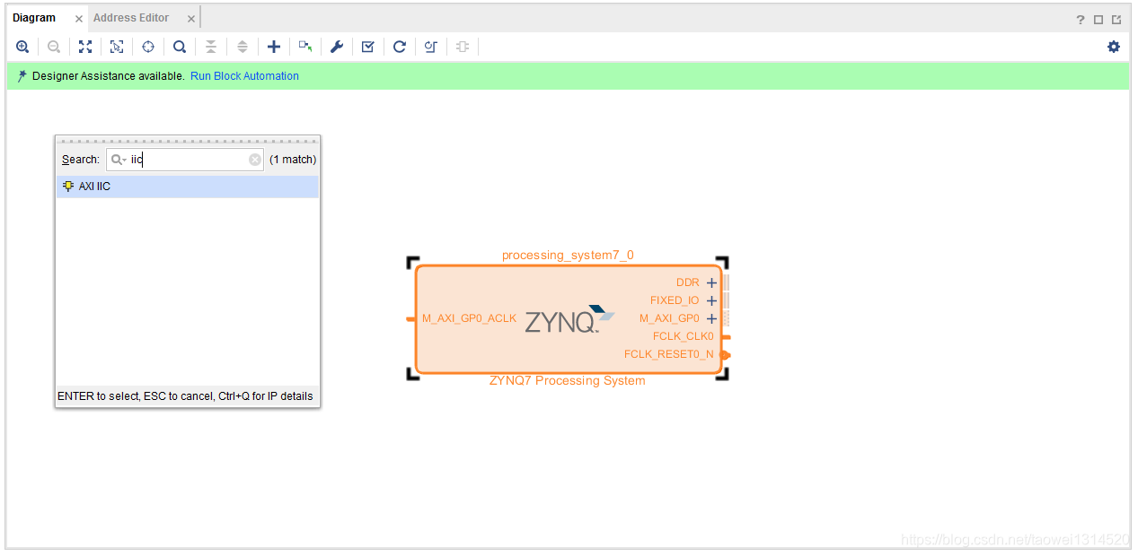
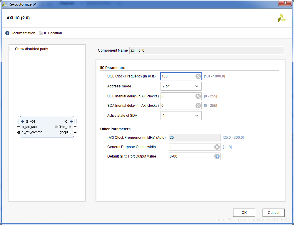
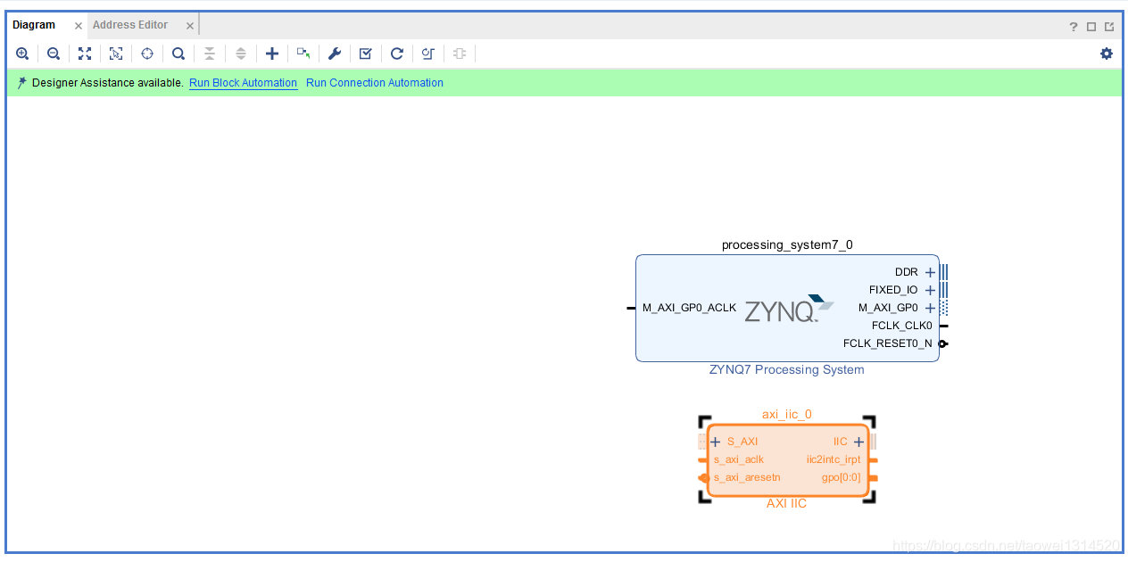
Step2 调用axi_iic核并设置SCL频率
我们选择默认配置(如果SCL是400K,这里可以改为400k)
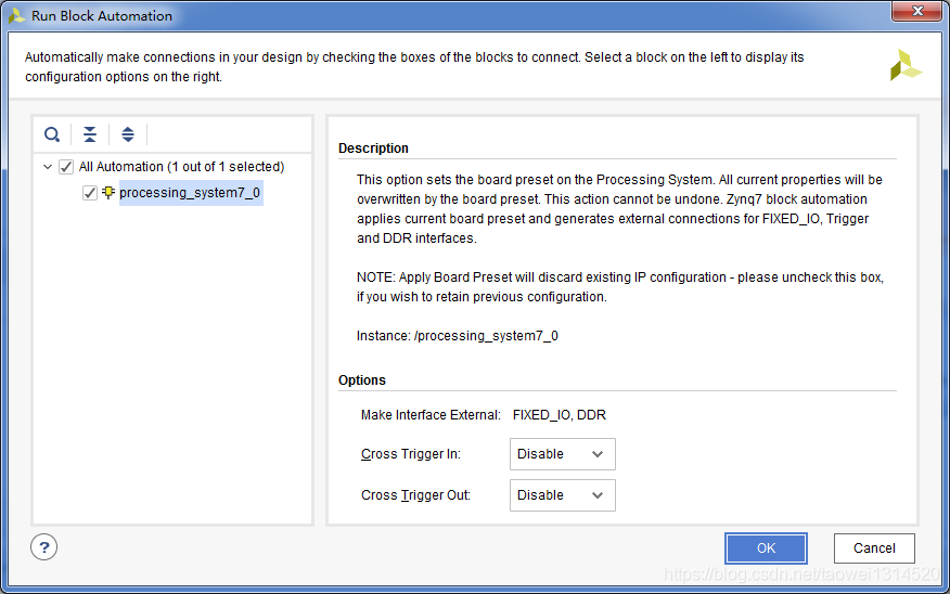
点击Run Block Automation 自动连线
引出的管脚如下图所示
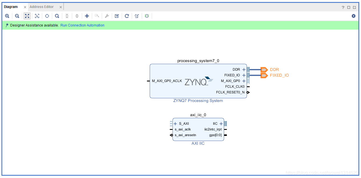
点击Run Connection Automation将所有的模块连接起来
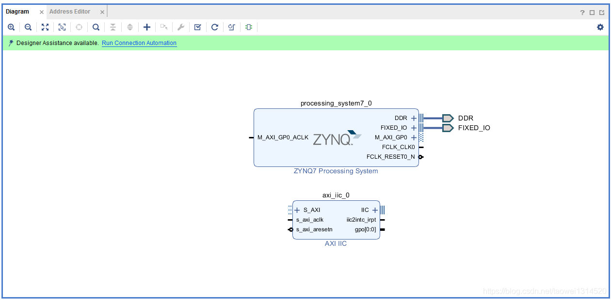
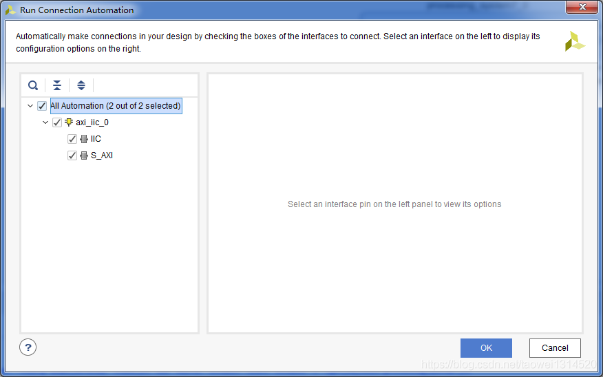
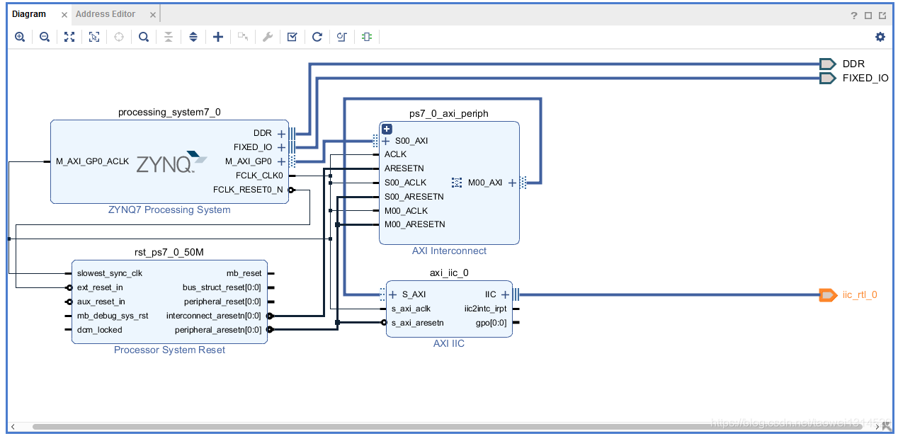
自动连线完成后,如下图所示
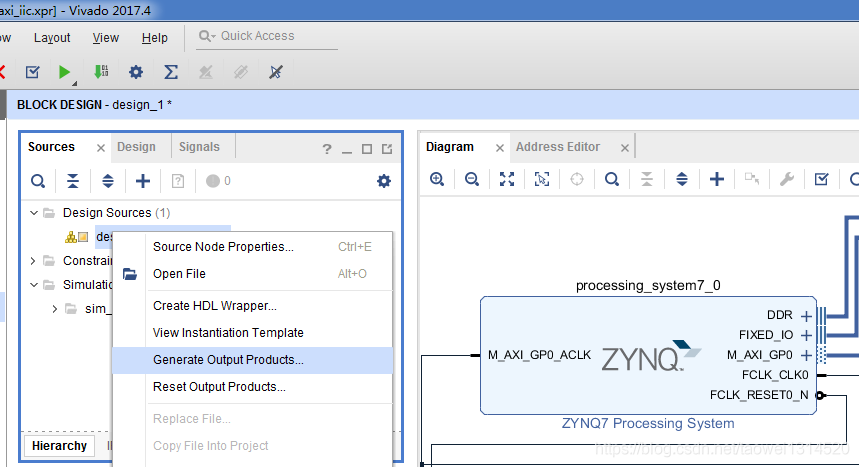
Step3 生成综合文件和生成顶层文件
生成综合文件
 、
、
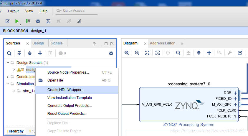
生成顶层文件
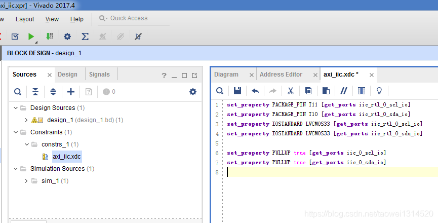
Step4 新建xdc文件并设置管脚
/******************************************************************************
*
* Copyright (C) 2002 - 2014 Xilinx, Inc.  All rights reserved.
*
* Permission is hereby granted, free of charge, to any person obtaining a copy
* of this software and associated documentation files (the "Software"), to deal
* in the Software without restriction, including without limitation the rights
* to use, copy, modify, merge, publish, distribute, sublicense, and/or sell
* copies of the Software, and to permit persons to whom the Software is
* furnished to do so, subject to the following conditions:
*
* The above copyright notice and this permission notice shall be included in
* all copies or substantial portions of the Software.
*
* Use of the Software is limited solely to applications:
* (a) running on a Xilinx device, or
* (b) that interact with a Xilinx device through a bus or interconnect.
*
* THE SOFTWARE IS PROVIDED "AS IS", WITHOUT WARRANTY OF ANY KIND, EXPRESS OR
* IMPLIED, INCLUDING BUT NOT LIMITED TO THE WARRANTIES OF MERCHANTABILITY,
* FITNESS FOR A PARTICULAR PURPOSE AND NONINFRINGEMENT. IN NO EVENT SHALL
* XILINX  BE LIABLE FOR ANY CLAIM, DAMAGES OR OTHER LIABILITY,
* WHETHER IN AN ACTION OF CONTRACT, TORT OR OTHERWISE, ARISING FROM, OUT OF
* OR IN CONNECTION WITH THE SOFTWARE OR THE USE OR OTHER DEALINGS IN THE
* SOFTWARE.
*
* Except as contained in this notice, the name of the Xilinx shall not be used
* in advertising or otherwise to promote the sale, use or other dealings in
* this Software without prior written authorization from Xilinx.
*
******************************************************************************/
/*****************************************************************************/
/**
* @file xiic_low_level_eeprom_example.c
*
* This file consists of a polled mode design example which uses the Xilinx
* IIC device and low-level driver to exercise the EEPROM.
*
* This example writes/reads from the lower 256 bytes of the IIC EEPROMS. Please
* refer to the datasheets of the IIC EEPROM's for details about the internal
* addressing and page size of these devices.
*
* The XIic_Send() API is used to transmit the data and XIic_Recv() API is used
* to receive the data.
*
* This example is tested on ML300/ML310/ML403/ML501/ML507/ML510/ML605/SP601 and
* SP605 Xilinx boards.
*
* The ML310/ML410/ML510 boards have a on-board 64 Kb serial IIC EEPROM
* (Microchip 24LC64A). The WP pin of the IIC EEPROM is hardwired to ground on
* this board.
*
* The ML300 board has an on-board 32 Kb serial IIC EEPROM(Microchip 24LC32A).
* The WP pin of the IIC EEPROM has to be connected to ground for this example.
* The WP is connected to pin Y3 of the FPGA.
*
* The ML403 board has an on-board 4 Kb serial IIC EEPROM(Microchip 24LC04A).
* The WP pin of the IIC EEPROM is hardwired to ground on this board.
*
* The ML501/ML505/ML507/ML605/SP601/SP605 boards have an on-board 8 Kb serial
* IIC EEPROM(STM M24C08). The WP pin of the IIC EEPROM is hardwired to
* ground on these boards.
*
* The AddressType for ML300/ML310/ML410/ML510 boards should be u16 as the
* address pointer in the on board EEPROM is 2 bytes.
*
* The AddressType for ML403/ML501/ML505/ML507/ML605/SP601/SP605 boards should
* be u8 as the address pointer for the on board EEPROM is 1 byte.
*
* The 7 bit IIC Slave address of the IIC EEPROM on the ML300/ML310/ML403/ML410/
* ML501/ML505/ML507/ML510 boards is 0x50.
* The 7 bit IIC Slave address of the IIC EEPROM on the ML605/SP601/SP605 boards
* is 0x54.
* Refer to the User Guide's of the respective boards for further information
* about the IIC slave address of IIC EEPROM's.
*
* The define EEPROM_ADDRESS in this file needs to be changed depending on
* the board on which this example is to be run.
*
* This code assumes that no Operating System is being used.
*
* @note		None
*
*
* MODIFICATION HISTORY:
*
* Ver	Who  Date	 Changes
* ----- ---- -------- -----------------------------------------------
* 1.00a jhl  09/10/03 Created
* 1.00a sv   05/09/05 Minor changes to comply to Doxygen and coding guidelines
* 1.00a mta  03/09/06 Minor updates due to changes in the low level driver for
*		      supporting repeated start functionality.
* 2.00a sdm  09/22/09 Converted all register accesses to 32 bit access and minor
*		      modifications as per coding guidelines.
* 2.01a ktn  03/17/10 Updated the information about the EEPROM's used on
*		      ML605/SP601/SP605 boards. Updated the example so that it
*		      can be used to access the entire IIC EEPROM for devices
*		      like M24C04/M24C08 that use LSB bits of the IIC device
*		      select code (IIC slave address) to specify the higher
*		      address bits of the EEPROM internal address.
* 2.01a sdm  06/13/11 Updated the example to flush the Tx FIFO when waiting for
*		      the previous command to be completed for CR612546.
* 3.4   ms   01/23/17 Added xil_printf statement in main function to
*                     ensure that "Successfully ran" and "Failed" strings
*                     are available in all examples. This is a fix for
*                     CR-965028.
*
*
******************************************************************************//***************************** Include Files *********************************/#include "xparameters.h"
#include "xiic.h"
#include "xil_io.h"
#include "xil_printf.h"/************************** Constant Definitions *****************************//** The following constants map to the XPAR parameters created in the* xparameters.h file. They are defined here such that a user can easily* change all the needed parameters in one place.*/
#define IIC_BASE_ADDRESS	XPAR_IIC_0_BASEADDR/** The following constant defines the address of the IIC Slave device on the* IIC bus. Note that since the address is only 7 bits, this constant is the* address divided by 2.* The 7 bit IIC Slave address of the IIC EEPROM on the ML300/ML310/ML403/ML410/* ML501/ML505/ML507/ML510 boards is 0x50. The 7 bit IIC Slave address of the* IIC EEPROM on the ML605/SP601/SP605 boards is 0x54.* Please refer the User Guide's of the respective boards for further* information about the IIC slave address of IIC EEPROM's.*/
#define EEPROM_ADDRESS	0x57	 /* 0xA0 as an 8 bit number *//** The page size determines how much data should be written at a time.* The ML300 board supports a page size of 32 and 16* The write function should be called with this as a maximum byte count.*/
#define PAGE_SIZE	16/** The Starting address in the IIC EEPROM on which this test is performed*/
#define EEPROM_TEST_START_ADDRESS	0/**************************** Type Definitions *******************************//** The AddressType for ML300/ML310/ML510 boards should be u16 as the address* pointer in the on board EEPROM is 2 bytes.* The AddressType for ML403/ML501/ML505/ML507/ML605/SP601/SP605 boards should* be u8 as the address pointer in the on board EEPROM is 1 bytes.*/
typedef u16 AddressType;/***************** Macros (Inline Functions) Definitions *********************//************************** Function Prototypes ******************************/int IicLowLevelEeprom();int ReadWriteVerify(AddressType Address);unsigned EepromWriteByte(AddressType Address, u8 *BufferPtr, u16 ByteCount);unsigned EepromReadByte(AddressType Address, u8 *BufferPtr, u16 ByteCount);/************************** Variable Definitions **************************/int ErrorCount;			  /* The Error Count */u8 WriteBuffer[PAGE_SIZE];	  /* Write buffer for writing a page */
u8 ReadBuffer[PAGE_SIZE];	  /* Read buffer for reading a page */
u8 ReadBufferAll[PAGE_SIZE * 4];  /* Buffer used for reading all the data */u8 EepromIicAddr;		  /* Variable for storing Eeprom IIC address *//*****************************************************************************/
/**
* Main function to call the low level EEPROM example.
*
* @param	None.
*
* @return	XST_SUCCESS if successful, XST_FAILURE if unsuccessful.
*
* @note		None.
*
******************************************************************************/
int main(void)
{int Status;/** Run the Low Level EEPROM example.*/Status = IicLowLevelEeprom();if (Status != XST_SUCCESS) {xil_printf("IIC lowlevel eeprom Example Failed\r\n");return XST_FAILURE;}xil_printf("Successfully ran IIC lowlevel eeprom Example\r\n");return XST_SUCCESS;
}/*****************************************************************************/
/**
* The function uses the low level driver of IIC to read and write to the
* IIC EEPROM board. The addresses tested are from 128 to 192.
*
* @param	None.
*
* @return	XST_SUCCESS if successful, XST_FAILURE if unsuccessful.
*
* @note		None.
*
****************************************************************************/
int IicLowLevelEeprom()
{int Status;unsigned BytesRead;EepromIicAddr = EEPROM_ADDRESS;/** Read, write and verify a page of data at the specified address.*/Status = ReadWriteVerify(EEPROM_TEST_START_ADDRESS);if (Status != XST_SUCCESS) {ErrorCount++;}return Status;
}/*****************************************************************************/
/**
* This function writes, reads, and verifies the read to the IIC EEPROM.  It
* does the write as a single page write, performs a buffered read, and also
* performs byte reads.
*
* @param	Address is the starting address of the page in the EEPROM device
*		to which the data is to be written.
*
* @return	 XST_FAILURE if the test fails, XST_SUCCESS if the test passes.
*
* @note 	None.
*
****************************************************************************/
int ReadWriteVerify(AddressType Address)
{unsigned BytesWritten;unsigned BytesRead;int Index;/** Initialize the data to written and the read buffer.*/for (Index = 0; Index < PAGE_SIZE; Index++) {WriteBuffer[Index] = Index;ReadBuffer[Index] = 0;}/** Write to the EEPROM.*/BytesWritten = EepromWriteByte(Address, WriteBuffer, PAGE_SIZE);if (BytesWritten != PAGE_SIZE) {return XST_FAILURE;}/** Read from the EEPROM.*/BytesRead = EepromReadByte(Address, ReadBuffer, PAGE_SIZE);if (BytesRead != PAGE_SIZE) {return XST_FAILURE;}//printf datafor (Index = 0; Index < PAGE_SIZE; Index++){xil_printf("0x%04x\r\n",ReadBuffer[Index]);}/** Read each byte one at a time and verify.*/for (Index = 0; Index < PAGE_SIZE; Index++){if (ReadBuffer[Index] != WriteBuffer[Index]) {return XST_FAILURE;}}return XST_SUCCESS;
}/*****************************************************************************/
/**
* This function writes a buffer of bytes to the IIC serial EEPROM.
*
* @param	Address contains the address in the EEPROM to write to.
* @param	BufferPtr contains the address of the data to write.
* @param	ByteCount contains the number of bytes in the buffer to be written.
*		Note that this should not exceed the page size of the EEPROM as
*		noted by the constant PAGE_SIZE.
*
* @return	The number of bytes written, a value less than that which was
*		specified as an input indicates an error.
*
* @note		None.
*
****************************************************************************/
unsigned EepromWriteByte(AddressType Address, u8 *BufferPtr, u16 ByteCount)
{volatile unsigned SentByteCount;volatile unsigned AckByteCount;u8 WriteBuffer[sizeof(Address) + PAGE_SIZE];int Index;/** A temporary write buffer must be used which contains both the address* and the data to be written, put the address in first based upon the* size of the address for the EEPROM.*/if (sizeof(AddressType) == 2) {WriteBuffer[0] = (u8)(Address >> 8);WriteBuffer[1] = (u8)(Address);} else if (sizeof(AddressType) == 1) {WriteBuffer[0] = (u8)(Address);EepromIicAddr |= (EEPROM_TEST_START_ADDRESS >> 8) & 0x7;}/** Put the data in the write buffer following the address.*/for (Index = 0; Index < ByteCount; Index++) {WriteBuffer[sizeof(Address) + Index] = BufferPtr[Index];}/** Set the address register to the specified address by writing* the address to the device, this must be tried until it succeeds* because a previous write to the device could be pending and it* will not ack until that write is complete.*/do {SentByteCount = XIic_Send(IIC_BASE_ADDRESS,EepromIicAddr,(u8 *)&Address, sizeof(Address),XIIC_STOP);if (SentByteCount != sizeof(Address)) {/* Send is aborted so reset Tx FIFO */XIic_WriteReg(IIC_BASE_ADDRESS,  XIIC_CR_REG_OFFSET,XIIC_CR_TX_FIFO_RESET_MASK);XIic_WriteReg(IIC_BASE_ADDRESS, XIIC_CR_REG_OFFSET,XIIC_CR_ENABLE_DEVICE_MASK);}} while (SentByteCount != sizeof(Address));/** Write a page of data at the specified address to the EEPROM.*/SentByteCount = XIic_Send(IIC_BASE_ADDRESS, EepromIicAddr,WriteBuffer, sizeof(Address) + PAGE_SIZE,XIIC_STOP);/** Wait for the write to be complete by trying to do a write and* the device will not ack if the write is still active.*/do {AckByteCount = XIic_Send(IIC_BASE_ADDRESS, EepromIicAddr,(u8 *)&Address, sizeof(Address),XIIC_STOP);if (AckByteCount != sizeof(Address)) {/* Send is aborted so reset Tx FIFO */XIic_WriteReg(IIC_BASE_ADDRESS,  XIIC_CR_REG_OFFSET,XIIC_CR_TX_FIFO_RESET_MASK);XIic_WriteReg(IIC_BASE_ADDRESS, XIIC_CR_REG_OFFSET,XIIC_CR_ENABLE_DEVICE_MASK);}} while (AckByteCount != sizeof(Address));/** Return the number of bytes written to the EEPROM*/return SentByteCount - sizeof(Address);
}/*****************************************************************************/
/**
* This function reads a number of bytes from the IIC serial EEPROM into a
* specified buffer.
*
* @param	Address contains the address in the EEPROM to read from.
* @param	BufferPtr contains the address of the data buffer to be filled.
* @param	ByteCount contains the number of bytes in the buffer to be read.
*		This value is not constrained by the page size of the device
*		such that up to 64K may be read in one call.
*
* @return	The number of bytes read. A value less than the specified input
*		value indicates an error.
*
* @note		None.
*
****************************************************************************/
unsigned EepromReadByte(AddressType Address, u8 *BufferPtr, u16 ByteCount)
{volatile unsigned ReceivedByteCount;u16 StatusReg;/** Set the address register to the specified address by writing* the address to the device, this must be tried until it succeeds* because a previous write to the device could be pending and it* will not ack until that write is complete.*/do {StatusReg = XIic_ReadReg(IIC_BASE_ADDRESS, XIIC_SR_REG_OFFSET);if(!(StatusReg & XIIC_SR_BUS_BUSY_MASK)) {ReceivedByteCount = XIic_Send(IIC_BASE_ADDRESS,EepromIicAddr,(u8 *)&Address,sizeof(Address),XIIC_STOP);if (ReceivedByteCount != sizeof(Address)) {/* Send is aborted so reset Tx FIFO */XIic_WriteReg(IIC_BASE_ADDRESS,XIIC_CR_REG_OFFSET,XIIC_CR_TX_FIFO_RESET_MASK);XIic_WriteReg(IIC_BASE_ADDRESS,XIIC_CR_REG_OFFSET,XIIC_CR_ENABLE_DEVICE_MASK);}}} while (ReceivedByteCount != sizeof(Address));/** Read the number of bytes at the specified address from the EEPROM.*/ReceivedByteCount = XIic_Recv(IIC_BASE_ADDRESS, EepromIicAddr,BufferPtr, ByteCount, XIIC_STOP);/** Return the number of bytes read from the EEPROM.*/return ReceivedByteCount;
}
复制完成后如下图所示
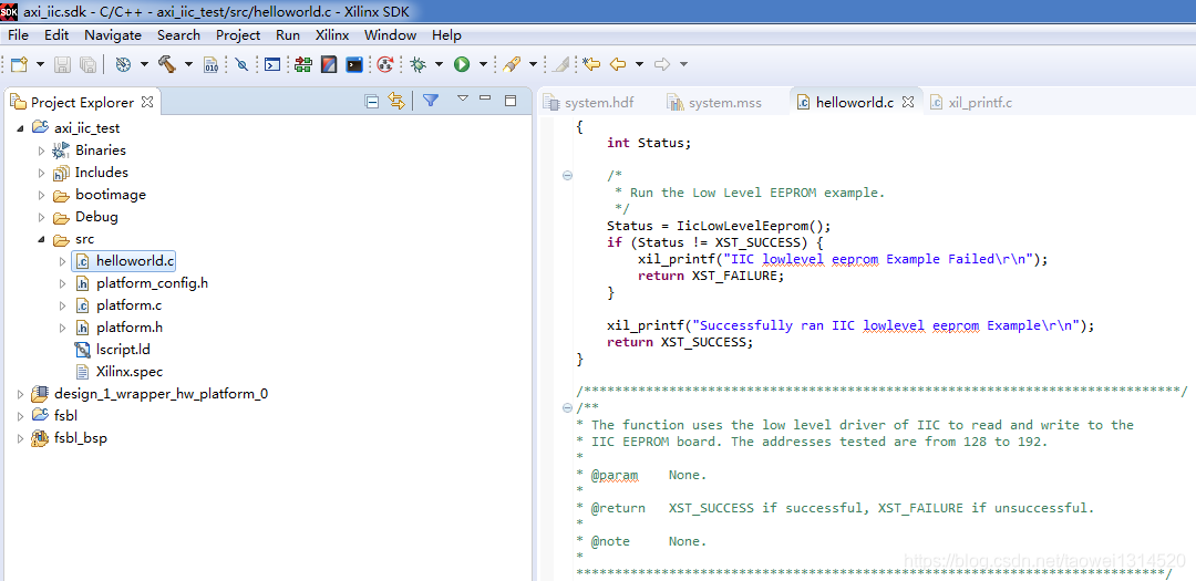
这个程序比较简单只对重要的地方分析一下
这里是24C32的原理图
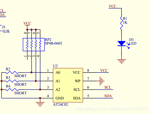
可以看到如果不包含读写位R/W一共七位数据,也就是 1010111 十六进制是0x57(可以看到eeprom的设备地址为0x57)
/***************************** Include Files *********************************/#include "xparameters.h"
#include "xiic.h"
#include "xil_io.h"
#include "xil_printf.h"/************************** Constant Definitions *****************************//** The following constants map to the XPAR parameters created in the* xparameters.h file. They are defined here such that a user can easily* change all the needed parameters in one place.*/
#define IIC_BASE_ADDRESS	XPAR_IIC_0_BASEADDR/** The following constant defines the address of the IIC Slave device on the* IIC bus. Note that since the address is only 7 bits, this constant is the* address divided by 2.* The 7 bit IIC Slave address of the IIC EEPROM on the ML300/ML310/ML403/ML410/* ML501/ML505/ML507/ML510 boards is 0x50. The 7 bit IIC Slave address of the* IIC EEPROM on the ML605/SP601/SP605 boards is 0x54.* Please refer the User Guide's of the respective boards for further* information about the IIC slave address of IIC EEPROM's.*/
#define EEPROM_ADDRESS	0x57	 /* 0xA0 as an 8 bit number *//** The page size determines how much data should be written at a time.* The ML300 board supports a page size of 32 and 16* The write function should be called with this as a maximum byte count.
这个往写buffer里面填充0~15数据
/** Initialize the data to written and the read buffer.*/for (Index = 0; Index < PAGE_SIZE; Index++) {WriteBuffer[Index] = Index;ReadBuffer[Index] = 0;}
将0~15数据写入到eeprom中
/** Write to the EEPROM.*/BytesWritten = EepromWriteByte(Address, WriteBuffer, PAGE_SIZE);if (BytesWritten != PAGE_SIZE) {return XST_FAILURE;}将写入到eeprom中的数据读出并打印出来
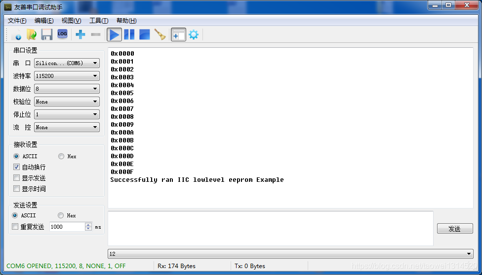
/** Read from the EEPROM.*/BytesRead = EepromReadByte(Address, ReadBuffer, PAGE_SIZE);if (BytesRead != PAGE_SIZE) {return XST_FAILURE;}//printf datafor (Index = 0; Index < PAGE_SIZE; Index++){xil_printf("0x%04x\r\n",ReadBuffer[Index]);}
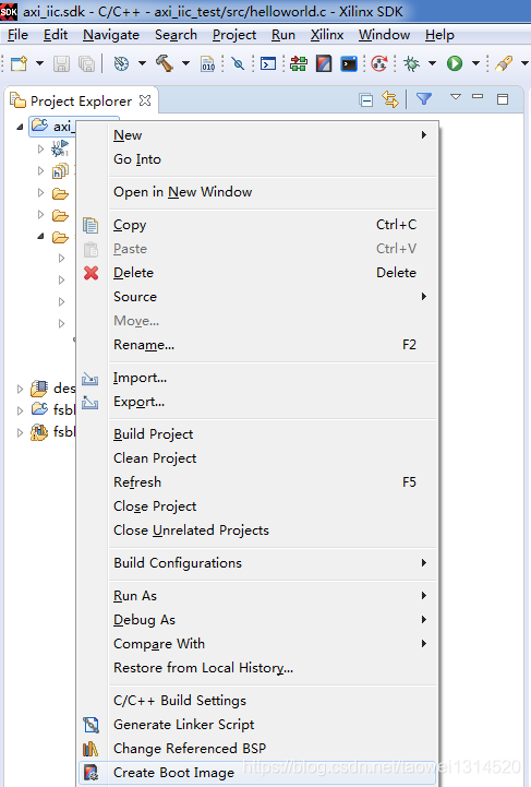
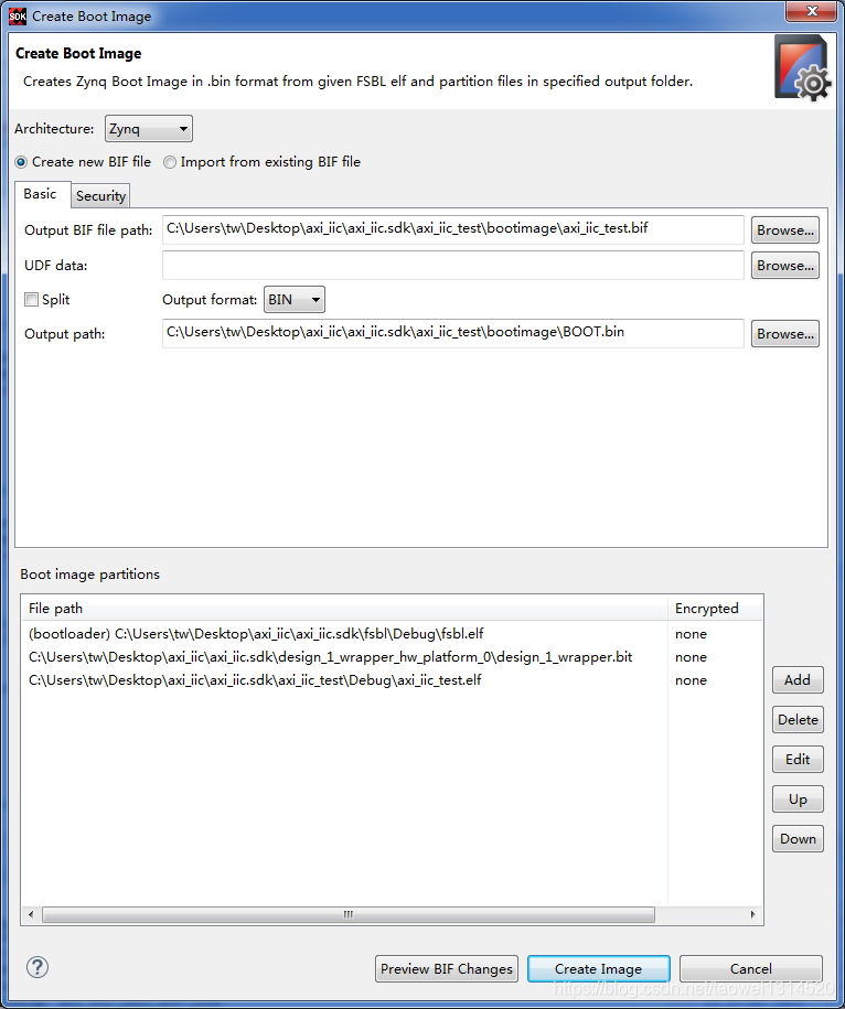
Step8 生成一个BOOT.bin文件放到SD卡里运行
右击工程选择Create Boot Image
点击 Create Image 生成BOOT.bin文件
开发板硬件连接

串口打印输出
本文来自互联网用户投稿,文章观点仅代表作者本人,不代表本站立场,不承担相关法律责任。如若转载,请注明出处。 如若内容造成侵权/违法违规/事实不符,请点击【内容举报】进行投诉反馈!