华为 HCIP 实验 - ‘ MPLS -VPN ’ _ MPLS VPN配置
目录
第一章 MPLS VPN配置
实验 1-2 MPLS VPN配置
学习目的
拓扑图
场景
学习任务
步骤一.基本配置与IP编址
步骤二.配置运营商网络单区域OSPF
步骤三.配置运营商网络边缘设备的VPN实例
步骤四.配置客户网络边缘设备与运营商网络边缘设备使用BGP协议传递路由
步骤五.配置运营商网络设备使用MP-BGP协议传递客户的私网路由
步骤六.配置运营商网络设备使用MPLS LDP协议转发客户的私网数据
附加实验: 思考并验证
最终设备配置
第一章 MPLS VPN配置
实验 1-2 MPLS VPN配置
学习目的
·掌握MPLS VPN实例的配置方法
·掌握MP-BGP的配置方法
·掌握MPLS LDP的配置方法
·了解MPLS VPN路由传递与数据转发的过程
拓扑图
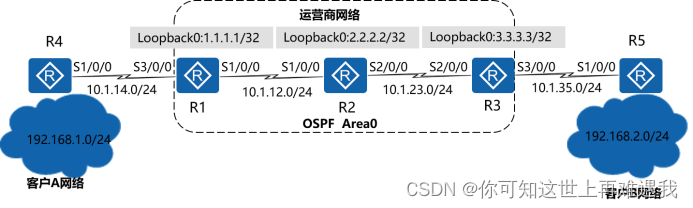
图1-2 MPLS VPN配置
场景
某公司有两个网络,分别是网络A与网络B,该公司希望两个网络内的员工能通过私网路由相互访问。该公司希望在网络边缘设备上使用BGP协议将私网路由发送给运营商网络。运营商通过MP-BGP实现私网路由在公共网络上的传递,同时使用MPLS VPN技术保证客户网络信息的安全性和私密性。
学习任务
步骤一.基本配置与IP编址
给所有路由器配置IP地址和掩码。
system-view Enter system view, return user view with Ctrl+Z.
[Huawei]sysname R1
[R1]interface Serial 1/0/0
[R1-Serial1/0/0]ip address 10.1.12.1 24
[R1-Serial1/0/0]quit
[R1]interface Serial 3/0/0
[R1-Serial3/0/0]ip address 10.1.14.1 24
[R1-Serial3/0/0]quit
[R1]interface LoopBack 0
[R1-LoopBack0]ip address 1.1.1.1 32
system-view Enter system view, return user view with Ctrl+Z.
[Huawei]sysname R2
[R2]interface Serial 1/0/0
[R2-Serial1/0/0]ip address 10.1.12.2 24
[R2-Serial1/0/0]quit
[R2]interface Serial 2/0/0
[R2-Serial2/0/0]ip address 10.1.23.2 24
[R1-Serial2/0/0]quit
[R2]interface LoopBack 0
[R2-LoopBack0]ip address 2.2.2.2 32
system-view Enter system view, return user view with Ctrl+Z.
[Huawei]sysname R3
[R3]interface Serial 2/0/0
[R3-Serial2/0/0]ip address 10.1.23.3 24
[R3-Serial2/0/0]quit
[R3]interface Serial 3/0/0
[R3-Serial3/0/0]ip address 10.1.35.3 24
[R3-Serial3/0/0]quit
[R3]interface LoopBack 0
[R3-LoopBack0]ip address 3.3.3.3 32
system-view Enter system view, return user view with Ctrl+Z.
[Huawei]sysname R4
[R4]interface Serial 1/0/0
[R4-Serial1/0/0]ip address 10.1.14.4 24
[R4-Serial1/0/0]quit
[R4]interface LoopBack 0
[R4-LoopBack0]ip address 192.168.1.1 24
system-view Enter system view, return user view with Ctrl+Z.
[Huawei]sysname R5
[R5]interface Serial 1/0/0
[R5-Serial1/0/0]ip address 10.1.35.5 24
[R5-Serial1/0/0]quit
[R5]interface LoopBack 0
[R5-LoopBack0]ip address 192.168.2.1 24
配置完成后,请自行测试直连链路的连通性。
步骤二.配置运营商网络单区域OSPF
配置10.1.12.0/24、10.1.23.0/24两个网段以及运营商网络各设备的LoopBack0接口属于OSPF Area0。
[R1]router id 1.1.1.1
[R1]ospf 1
[R1-ospf-1]area 0
[R1-ospf-1-area-0.0.0.0]network 10.1.12.0 0.0.0.255
[R1-ospf-1-area-0.0.0.0]network 1.1.1.1 0.0.0.0
[R2]router id 2.2.2.2
[R2]ospf 1
[R2-ospf-1]area 0
[R2-ospf-1-area-0.0.0.0]network 10.1.12.0 0.0.0.255
[R2-ospf-1-area-0.0.0.0]network 10.1.23.0 0.0.0.255
[R2-ospf-1-area-0.0.0.0]network 2.2.2.2 0.0.0.0
[R3]router id 3.3.3.3
[R3]ospf 1
[R3-ospf-1]area 0
[R3-ospf-1-area-0.0.0.0]network 10.1.23.0 0.0.0.255
[R3-ospf-1-area-0.0.0.0]network 3.3.3.3 0.0.0.0
配置完成后,分别在R1,R2与R3上查看OSPF邻居关系的建立情况。
[R1]display ospf peer brief
OSPF Process 1 with Router ID 1.1.1.1
Peer Statistic Information
----------------------------------------------------------------------------
Area Id Interface Neighbor id State
0.0.0.0 Serial1/0/0 2.2.2.2 Full
----------------------------------------------------------------------------
Total Peer(s): 1
[R2]display ospf peer brief
OSPF Process 1 with Router ID 2.2.2.2
Peer Statistic Information
----------------------------------------------------------------------------
Area Id Interface Neighbor id State
0.0.0.0 Serial1/0/0 1.1.1.1 Full
0.0.0.0 Serial2/0/0 3.3.3.3 Full
----------------------------------------------------------------------------
Total Peer(s): 2
[R3]display ospf peer brief
OSPF Process 1 with Router ID 3.3.3.3
Peer Statistic Information
----------------------------------------------------------------------------
Area Id Interface Neighbor id State
0.0.0.0 Serial2/0/0 2.2.2.2 Full
----------------------------------------------------------------------------
Total Peer(s): 1
步骤三.配置运营商网络边缘设备的VPN实例
在R1与R3上分别为客户A网络与客户B网络配置VPN实例。分配客户A网络的VPN实例为VPN1,RD值为1:1,Export Target与Import Target为1:2;分配给客户B网络的VPN实例为VPN2,RD值为2:2,Export Target与Import Target为1:2。
[R1]ip vpn-instance VPN1
[R1-vpn-instance-VPN1]route-distinguisher 1:1
[R1-vpn-instance-VPN1-af-ipv4]vpn-target 1:2 both
[R1-vpn-instance-VPN1-af-ipv4]quit
[R1-vpn-instance-VPN1]quit
[R1]interface Serial 3/0/0
[R1-Serial3/0/0]ip binding vpn-instance VPN1
Info: All IPv4 related configurations on this interface are removed!
Info: All IPv6 related configurations on this interface are removed!
[R1-Serial3/0/0] ip address 10.1.14.1 24
[R3]ip vpn-instance VPN2
[R3-vpn-instance-VPN2]route-distinguisher 2:2
[R3-vpn-instance-VPN2-af-ipv4]vpn-target 1:2 both
[R3-vpn-instance-VPN2-af-ipv4]quit
[R3-vpn-instance-VPN2]quit
[R3]interface Serial 3/0/0
[R3-Serial3/0/0]ip binding vpn-instance VPN2
Info: All IPv4 related configurations on this interface are removed!
Info: All IPv6 related configurations on this interface are removed!
[R3-Serial3/0/0]ip address 10.1.35.3 24
配置完成后,分别在R1与R3上查看配置的VPN实例。
[R1]display ip vpn-instance verbose
Total VPN-Instances configured : 1
Total IPv4 VPN-Instances configured : 1
Total IPv6 VPN-Instances configured : 0
VPN-Instance Name and ID : VPN1, 1
Interfaces : Serial3/0/0
Address family ipv4
Create date : 2016/09/20 14:51:08
Up time : 0 days, 00 hours, 09 minutes and 34 seconds
Route Distinguisher : 1:1
Export VPN Targets : 1:2
Import VPN Targets : 1:2
Label Policy : label per route
Log Interval : 5
[R3]display ip vpn-instance verbose
Total VPN-Instances configured : 1
Total IPv4 VPN-Instances configured : 1
Total IPv6 VPN-Instances configured : 0
VPN-Instance Name and ID : VPN2, 1
Interfaces : Serial3/0/0
Address family ipv4
Create date : 2016/09/20 15:02:52
Up time : 0 days, 00 hours, 05 minutes and 32 seconds
Route Distinguisher : 2:2
Export VPN Targets : 1:2
Import VPN Targets : 1:2
Label Policy : label per route
Log Interval : 5
步骤四.配置客户网络边缘设备与运营商网络边缘设备使用BGP协议传递路由
客户A网络的AS号为14,运营商网络的AS号为123,客户B网络的AS号为35。客户网络边缘设备与运营商网络边缘设备建立BGP的邻居关系,使客户私网路由通过BGP协议通告给运营商网络边缘设备。
[R1]bgp 123
[R1-bgp]ipv4-family vpn-instance VPN1
[R1-bgp-VPN1]peer 10.1.14.4 as-number 14
[R3]bgp 123
[R3-bgp]ipv4-family vpn-instance VPN2
[R3-bgp-VPN2]peer 10.1.35.5 as-number 35
[R4]bgp 14
[R4-bgp]peer 10.1.14.1 as-number 123
[R4-bgp]network 192.168.1.0 24
[R5]bgp 35
[R5-bgp]peer 10.1.35.3 as-number 123
[R5-bgp]network 192.168.2.0 24
配置完成后,分别在R1与R4,R3与R5上查看BGP邻居关系的建立情况。
[R1]display bgp vpnv4 vpn-instance VPN1 peer
BGP local router ID : 1.1.1.1
Local AS number : 123
VPN-Instance VPN1, Router ID 1.1.1.1:
Total number of peers : 1 Peers in established state : 1
Peer V AS MsgRcvd MsgSent OutQ Up/Down State PrefRcv
10.1.14.4 4 14 7 8 0 00:05:21 Established 0
[R4]display bgp peer
BGP local router ID : 10.1.14.4
Local AS number : 14
Total number of peers : 1 Peers in established state : 1
Peer V AS MsgRcvd MsgSent OutQ Up/Down State PrefRcv
10.1.14.1 4 123 4 6 0 00:02:56 Established 0
[R3]display bgp vpnv4 vpn-instance VPN2 peer
BGP local router ID : 3.3.3.3
Local AS number : 123
VPN-Instance VPN2, Router ID 3.3.3.3:
Total number of peers : 1 Peers in established state : 1
Peer V AS MsgRcvd MsgSent OutQ Up/Down State PrefRcv
10.1.35.5 4 35 7 8 0 00:05:16 Established 0
[R5]display bgp peer
BGP local router ID : 192.168.1.1
Local AS number : 35
Total number of peers : 1 Peers in established state : 1
Peer V AS MsgRcvd MsgSent OutQ Up/Down State PrefRcv
10.1.35.3 4 123 8 10 0 00:06:04 Established 0
分别在R1与R3上查看VPN路由表学到的客户网络的私网路由。
[R1]display ip routing-table vpn-instance VPN1
Route Flags: R - relay, D - download to fib
------------------------------------------------------------------------------
Routing Tables: VPN1
Destinations : 6 Routes : 6
Destination/Mask Proto Pre Cost Flags NextHop Interface
10.1.14.0/24 Direct 0 0 D 10.1.14.1 Serial3/0/0
10.1.14.1/32 Direct 0 0 D 127.0.0.1 Serial3/0/0
10.1.14.4/32 Direct 0 0 D 10.1.14.4 Serial3/0/0
10.1.14.255/32 Direct 0 0 D 127.0.0.1 Serial3/0/0
192.168.1.0/24 EBGP 255 0 D 10.1.14.4 Serial3/0/0
255.255.255.255/32 Direct 0 0 D 127.0.0.1 InLoopBack0
[R3]display ip routing-table vpn-instance VPN2
Route Flags: R - relay, D - download to fib
------------------------------------------------------------------------------
Routing Tables: VPN2
Destinations : 6 Routes : 6
Destination/Mask Proto Pre Cost Flags NextHop Interface
10.1.35.0/24 Direct 0 0 D 10.1.35.3 Serial3/0/0
10.1.35.3/32 Direct 0 0 D 127.0.0.1 Serial3/0/0
10.1.35.5/32 Direct 0 0 D 10.1.35.5 Serial3/0/0
10.1.35.255/32 Direct 0 0 D 127.0.0.1 Serial3/0/0
192.168.2.0/24 EBGP 255 0 D 10.1.35.5 Serial3/0/0
255.255.255.255/32 Direct 0 0 D 127.0.0.1 InLoopBack0
步骤五.配置运营商网络设备使用MP-BGP协议传递客户的私网路由
在R1与R3之间建立IBGP的邻居关系,采用MP-BGP协议在运营商网络中传递客户的私网路由。
[R1]bgp 123
[R1-bgp]peer 3.3.3.3 as-number 123
[R1-bgp]peer 3.3.3.3 connect-interface LoopBack 0
[R1-bgp]ipv4-family vpnv4 unicast
[R1-bgp-af-vpnv4]peer 3.3.3.3 enable
[R3]bgp 123
[R3-bgp]peer 1.1.1.1 as-number 123
[R3-bgp]peer 1.1.1.1 connect-interface LoopBack 0
[R3-bgp]ipv4-family vpnv4 unicast
[R3-bgp-af-vpnv4]peer 1.1.1.1 enable
配置完成后,分别在R1与R3上查看MP-BGP邻居关系的建立情况。
[R1]display bgp vpnv4 all peer
BGP local router ID : 1.1.1.1
Local AS number : 123
Total number of peers : 2 Peers in established state : 2
Peer V AS MsgRcvd MsgSent OutQ Up/Down State PrefRcv
3.3.3.3 4 123 4 7 0 00:02:10 Established 0
[R3]display bgp vpnv4 all peer
BGP local router ID : 3.3.3.3
Local AS number : 123
Total number of peers : 2 Peers in established state : 2
Peer V AS MsgRcvd MsgSent OutQ Up/Down State PrefRcv
1.1.1.1 4 123 5 6 0 00:03:22 Established 0
步骤六.配置运营商网络设备使用MPLS LDP协议转发客户的私网数据
在运营商网络的所有设备上开启MPLS LDP协议,使用标签转发客户网络的私网数据,达到用户数据与其他网络数据隔离的目的。
[R1]mpls lsr-id 1.1.1.1
[R1]mpls
[R1-mpls]mpls ldp
[R1-mpls-ldp]quit
[R1]interface Serial 1/0/0
[R1-Serial1/0/0]mpls
[R1-Serial1/0/0]mpls ldp
[R2]mpls lsr-id 2.2.2.2
[R2]mpls
[R2-mpls]mpls ldp
[R2-mpls-ldp]quit
[R2]interface s1/0/0
[R2-Serial1/0/0]mpls
[R2-Serial1/0/0]mpls ldp
[R2-Serial1/0/0]quit
[R2]interface s2/0/0
[R2-Serial2/0/0]mpls
[R2-Serial2/0/0]mpls ldp
[R3]mpls lsr-id 3.3.3.3
[R3]mpls
[R3-mpls]mpls ldp
[R3-mpls-ldp]quit
[R3]interface Serial 2/0/0
[R3-Serial2/0/0]mpls
[R3-Serial2/0/0]mpls ldp
配置完成后,分别在R1,R2与R3上查看MPLS LDP邻居关系的建立情况。
[R1]display mpls ldp peer
LDP Peer Information in Public network
A '*' before a peer means the peer is being deleted.
----------------------------------------------------------------------------
PeerID TransportAddress DiscoverySource
----------------------------------------------------------------------------
2.2.2.2:0 2.2.2.2 Serial1/0/0
----------------------------------------------------------------------------
TOTAL: 1 Peer(s) Found.
[R2]display mpls ldp peer
LDP Peer Information in Public network
A '*' before a peer means the peer is being deleted.
----------------------------------------------------------------------------
PeerID TransportAddress DiscoverySource
----------------------------------------------------------------------------
1.1.1.1:0 1.1.1.1 Serial1/0/0
3.3.3.3:0 3.3.3.3 Serial2/0/0
----------------------------------------------------------------------------
TOTAL: 2 Peer(s) Found.
[R3]display mpls ldp peer
LDP Peer Information in Public network
A '*' before a peer means the peer is being deleted.
----------------------------------------------------------------------------
PeerID TransportAddress DiscoverySource
----------------------------------------------------------------------------
2.2.2.2:0 2.2.2.2 Serial2/0/0
----------------------------------------------------------------------------
TOTAL: 1 Peer(s) Found.
步骤七.在客户网络边缘设备上检查A网络与B网络的连通性
分别在R4与R5上使用LoopBack0模拟客户网络的用户,使用Ping命令检查A网络与B网络的连通性。
ping -a 192.168.1.1 192.168.2.1 PING 192.168.2.1: 56 data bytes, press CTRL_C to break
Reply from 192.168.2.1: bytes=56 Sequence=1 ttl=252 time=106 ms
Reply from 192.168.2.1: bytes=56 Sequence=2 ttl=252 time=107 ms
Reply from 192.168.2.1: bytes=56 Sequence=3 ttl=252 time=106 ms
Reply from 192.168.2.1: bytes=56 Sequence=4 ttl=252 time=105 ms
Reply from 192.168.2.1: bytes=56 Sequence=5 ttl=252 time=106 ms
--- 192.168.2.1 ping statistics ---
5 packet(s) transmitted
5 packet(s) received
0.00% packet loss
round-trip min/avg/max = 105/106/107 ms
ping -a 192.168.2.1 192.168.1.1 PING 192.168.1.1: 56 data bytes, press CTRL_C to break
Reply from 192.168.1.1: bytes=56 Sequence=1 ttl=252 time=107 ms
Reply from 192.168.1.1: bytes=56 Sequence=2 ttl=252 time=105 ms
Reply from 192.168.1.1: bytes=56 Sequence=3 ttl=252 time=106 ms
Reply from 192.168.1.1: bytes=56 Sequence=4 ttl=252 time=106 ms
Reply from 192.168.1.1: bytes=56 Sequence=5 ttl=252 time=106 ms
--- 192.168.1.1 ping statistics ---
5 packet(s) transmitted
5 packet(s) received
0.00% packet loss
round-trip min/avg/max = 105/106/107 ms
分别在R4与R5上查看路由表中学习到的对端客户网络的私网路由。
display ip routing-table Route Flags: R - relay, D - download to fib
----------------------------------------------------------------------------Routing Tables: Public
Destinations : 12 Routes : 12
Destination/Mask Proto Pre Cost Flags NextHop Interface
10.1.14.0/24 Direct 0 0 D 10.1.14.4 Serial1/0/0
10.1.14.1/32 Direct 0 0 D 10.1.14.1 Serial1/0/0
10.1.14.4/32 Direct 0 0 D 127.0.0.1 Serial1/0/0
10.1.14.255/32 Direct 0 0 D 127.0.0.1 Serial1/0/0
127.0.0.0/8 Direct 0 0 D 127.0.0.1 InLoopBack0
127.0.0.1/32 Direct 0 0 D 127.0.0.1 InLoopBack0
127.255.255.255/32 Direct 0 0 D 127.0.0.1 InLoopBack0
192.168.1.0/24 Direct 0 0 D 192.168.1.1 LoopBack0
192.168.1.1/32 Direct 0 0 D 127.0.0.1 LoopBack0
192.168.1.255/32 Direct 0 0 D 127.0.0.1 LoopBack0
192.168.2.0/24 EBGP 255 0 D 10.1.14.1 Serial1/0/0
255.255.255.255/32 Direct 0 0 D 127.0.0.1 InLoopBack0
display ip routing-table Route Flags: R - relay, D - download to fib
----------------------------------------------------------------------------
Routing Tables: Public
Destinations : 12 Routes : 12
Destination/Mask Proto Pre Cost Flags NextHop Interface
10.1.35.0/24 Direct 0 0 D 10.1.35.5 Serial1/0/0
10.1.35.3/32 Direct 0 0 D 10.1.35.3 Serial1/0/0
10.1.35.5/32 Direct 0 0 D 127.0.0.1 Serial1/0/0
10.1.35.255/32 Direct 0 0 D 127.0.0.1 Serial1/0/0
127.0.0.0/8 Direct 0 0 D 127.0.0.1 InLoopBack0
127.0.0.1/32 Direct 0 0 D 127.0.0.1 InLoopBack0
127.255.255.255/32 Direct 0 0 D 127.0.0.1 InLoopBack0
192.168.1.0/24 EBGP 255 0 D 10.1.35.3 Serial1/0/0
192.168.2.0/24 Direct 0 0 D 192.168.2.1 LoopBack0
192.168.2.1/32 Direct 0 0 D 127.0.0.1 LoopBack0
192.168.2.255/32 Direct 0 0 D 127.0.0.1 LoopBack0
255.255.255.255/32 Direct 0 0 D 127.0.0.1 InLoopBack0
附加实验: 思考并验证
思考一下,在R1上新增了一个MPLS VPN的客户网络,如果要求实现与其他两个VPN客户网络的通信,该做哪些配置满足需求?
最终设备配置
display current-configuration [V200R007C00SPC600]
#
sysname R1
#
router id 1.1.1.1
#
ip vpn-instance VPN1
ipv4-family
route-distinguisher 1:1
vpn-target 1:2 export-extcommunity
vpn-target 1:2 import-extcommunity
#
mpls lsr-id 1.1.1.1
mpls
#
mpls ldp
#
interface Serial1/0/0
link-protocol ppp
ip address 10.1.12.1 255.255.255.0
mpls
mpls ldp
#
interface Serial3/0/0
link-protocol ppp
ip binding vpn-instance VPN1
ip address 10.1.14.1 255.255.255.0
#
interface LoopBack0
ip address 1.1.1.1 255.255.255.255
#
bgp 123
peer 3.3.3.3 as-number 123
peer 3.3.3.3 connect-interface LoopBack0
#
ipv4-family unicast
undo synchronization
peer 3.3.3.3 enable
#
ipv4-family vpnv4
policy vpn-target
peer 3.3.3.3 enable
#
ipv4-family vpn-instance VPN1
peer 10.1.14.4 as-number 14
#
ospf 1
area 0.0.0.0
network 1.1.1.1 0.0.0.0
network 10.1.12.0 0.0.0.255
#
return
display current-configuration [V200R007C00SPC600]
#
sysname R2
#
router id 2.2.2.2
#
mpls lsr-id 2.2.2.2
mpls
#
mpls ldp
#
interface Serial1/0/0
link-protocol ppp
ip address 10.1.12.2 255.255.255.0
mpls
mpls ldp
#
interface Serial2/0/0
link-protocol ppp
ip address 10.1.23.2 255.255.255.0
mpls
mpls ldp
#
interface LoopBack0
ip address 2.2.2.2 255.255.255.255
#
ospf 1
area 0.0.0.0
network 2.2.2.2 0.0.0.0
network 10.1.12.0 0.0.0.255
network 10.1.23.0 0.0.0.255
#
return
display current-configuration [V200R007C00SPC600]
#
sysname R3
#
router id 3.3.3.3
#
ip vpn-instance VPN2
ipv4-family
route-distinguisher 2:2
vpn-target 1:2 export-extcommunity
vpn-target 1:2 import-extcommunity
#
mpls lsr-id 3.3.3.3
mpls
#
mpls ldp
#
interface Serial2/0/0
link-protocol ppp
ip address 10.1.23.3 255.255.255.0
mpls
mpls ldp
#
interface Serial3/0/0
link-protocol ppp
ip binding vpn-instance VPN2
ip address 10.1.35.3 255.255.255.0
#
interface LoopBack0
ip address 3.3.3.3 255.255.255.255
#
bgp 123
peer 1.1.1.1 as-number 123
peer 1.1.1.1 connect-interface LoopBack0
#
ipv4-family unicast
undo synchronization
peer 1.1.1.1 enable
#
ipv4-family vpnv4
policy vpn-target
peer 1.1.1.1 enable
#
ipv4-family vpn-instance VPN2
peer 10.1.35.5 as-number 35
#
ospf 1
area 0.0.0.0
network 3.3.3.3 0.0.0.0
network 10.1.23.0 0.0.0.255
#
return
display current-configuration [V200R007C00SPC600]
#
sysname R4
#
interface Serial1/0/0
link-protocol ppp
ip address 10.1.14.4 255.255.255.0
#
interface LoopBack0
ip address 192.168.1.1 255.255.255.0
#
bgp 14
peer 10.1.14.1 as-number 123
#
ipv4-family unicast
undo synchronization
network 192.168.1.0
peer 10.1.14.1 enable
#
return
display current-configuration [V200R007C00SPC600]
#
sysname R5
#
interface Serial1/0/0
link-protocol ppp
ip address 10.1.35.5 255.255.255.0
#
interface LoopBack0
ip address 192.168.2.1 255.255.255.0
#
bgp 35
peer 10.1.35.3 as-number 123
#
ipv4-family unicast
undo synchronization
network 192.168.2.0
peer 10.1.35.3 enable
#
return
本文来自互联网用户投稿,文章观点仅代表作者本人,不代表本站立场,不承担相关法律责任。如若转载,请注明出处。 如若内容造成侵权/违法违规/事实不符,请点击【内容举报】进行投诉反馈!