TI F28335 系统时钟初始化总结
配置系统时钟
下图为F28335的振荡器和锁相环模块:
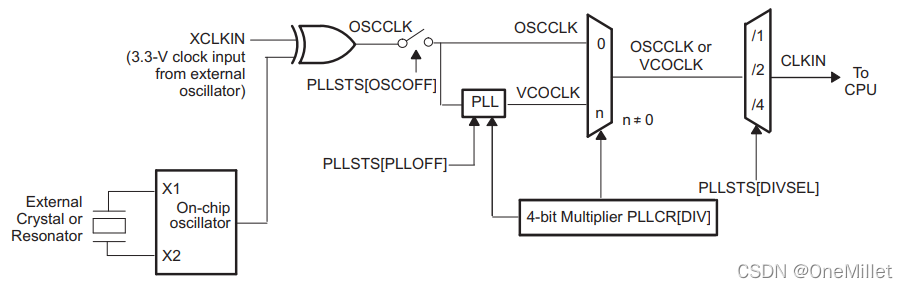
从图中可以看出,若要使时钟信号到达CPU,则需要清零PLLSTS[OSCOFF],然后由多路选择器来决定是信号直通还是通过锁相环倍频输出,若要使用锁相环,需要清零PLLSTS[PLLOFF]位,同时通过4-bit Multiplier PLLCR[DIV]配置倍频倍数,最后通过PLLSTS[DIVSEL]设置分频倍数后送到CPU。
下边以常用的30MHz无源晶体产生150MHz的系统时钟为例,作为说明。
首先找到需要配置的寄存器,于系统时钟相关的寄存器都在SysCtrlRegs大类下边,配置会用到如下位:
1、SysCtrlRegs.PLLSTS.bit.OSCOFF
2、SysCtrlRegs.PLLSTS.bit.PLLOFF
3、SysCtrlRegs.PLLCR.bit.DIV
4、SysCtrlRegs.PLLSTS.bit.DIVSEL
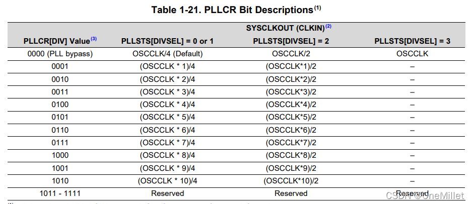
然后,根据150 = 30*(SysCtrlRegs.PLLCR.bit.DIV)/(SysCtrlRegs.PLLSTS.bit.DIVSEL)来配置两个寄存器的参数,其中,要注意SysCtrlRegs.PLLCR.bit.DIV的最大值只能是10,这里假设将SysCtrlRegs.PLLCR.bit.DIV设置位最大值,那么需要将SysCtrlRegs.PLLSTS.bit.DIVSEL设置为2.
其他配置描述:
TI原厂的源程序已经定义好了相关函数,在主函数中直接调用InitSysCtrl()即可,实际应用中我们只要改变DSP2833x_Examples.h文件中的宏定义数值DSP28_PLLCR和DSP28_DIVSEL的值即可改变系统时钟。
#define DSP28_PLLCR   10
#define DSP28_DIVSEL   2void
InitSysCtrl(void)
{//// Disable the watchdog//DisableDog();//// Initialize the PLL control: PLLCR and DIVSEL// DSP28_PLLCR and DSP28_DIVSEL are defined in DSP2833x_Examples.h//InitPll(DSP28_PLLCR,DSP28_DIVSEL);//// Initialize the peripheral clocks//InitPeripheralClocks();
}
void
InitPll(Uint16 val, Uint16 divsel)
{//// Make sure the PLL is not running in limp mode//if (SysCtrlRegs.PLLSTS.bit.MCLKSTS != 0){//// Missing external clock has been detected// Replace this line with a call to an appropriate// SystemShutdown(); function.//asm("        ESTOP0");}//// DIVSEL MUST be 0 before PLLCR can be changed from// 0x0000. It is set to 0 by an external reset XRSn// This puts us in 1/4//if (SysCtrlRegs.PLLSTS.bit.DIVSEL != 0){EALLOW;SysCtrlRegs.PLLSTS.bit.DIVSEL = 0;EDIS;}//// Change the PLLCR//if (SysCtrlRegs.PLLCR.bit.DIV != val){EALLOW;//// Before setting PLLCR turn off missing clock detect logic//SysCtrlRegs.PLLSTS.bit.MCLKOFF = 1;SysCtrlRegs.PLLCR.bit.DIV = val;EDIS;//// Optional: Wait for PLL to lock.// During this time the CPU will switch to OSCCLK/2 until// the PLL is stable.  Once the PLL is stable the CPU will// switch to the new PLL value.//// This time-to-lock is monitored by a PLL lock counter.//// Code is not required to sit and wait for the PLL to lock.// However, if the code does anything that is timing critical,// and requires the correct clock be locked, then it is best to// wait until this switching has completed.////// Wait for the PLL lock bit to be set.////// The watchdog should be disabled before this loop, or fed within// the loop via ServiceDog().////// Uncomment to disable the watchdog//DisableDog();while(SysCtrlRegs.PLLSTS.bit.PLLLOCKS != 1){//// Uncomment to service the watchdog////ServiceDog();}EALLOW;SysCtrlRegs.PLLSTS.bit.MCLKOFF = 0;EDIS;}//// If switching to 1/2//if((divsel == 1)||(divsel == 2)){EALLOW;SysCtrlRegs.PLLSTS.bit.DIVSEL = divsel;EDIS;}//// NOTE: ONLY USE THIS SETTING IF PLL IS BYPASSED (I.E. PLLCR = 0) OR OFF// If switching to 1/1// * First go to 1/2 and let the power settle//   The time required will depend on the system, this is only an example// * Then switch to 1/1//if(divsel == 3){EALLOW;SysCtrlRegs.PLLSTS.bit.DIVSEL = 2;DELAY_US(50L);SysCtrlRegs.PLLSTS.bit.DIVSEL = 3;EDIS;}
}
DSP2833x_Examples.h文件中的宏定义:
//#define DSP28_DIVSEL   0   // Enable /4 for SYSCLKOUT
//#define DSP28_DIVSEL   1 // Enable /4 for SYSCKOUT
#define DSP28_DIVSEL     2 // Enable /2 for SYSCLKOUT
//#define DSP28_DIVSEL     3 // Enable /1 for SYSCLKOUT#define DSP28_PLLCR   10
//#define DSP28_PLLCR    9
//#define DSP28_PLLCR    8
//#define DSP28_PLLCR    7
//#define DSP28_PLLCR    6
//#define DSP28_PLLCR    5
//#define DSP28_PLLCR    4
//#define DSP28_PLLCR    3
//#define DSP28_PLLCR    2
//#define DSP28_PLLCR    1
//#define DSP28_PLLCR    0  // PLL is bypassed in this mode
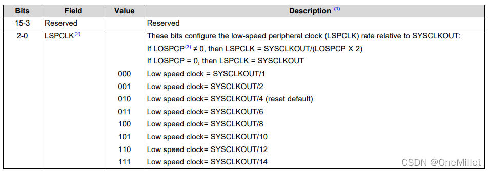
另外,为了方便控制功耗,F28335的每个外设都有独立的时钟使能开关,InitPeripheralClocks();函数中,默认把所有时钟打开,并把高速外设时钟的分频系数SysCtrlRegs.HISPCP.all和低速外设时钟的分频系数SysCtrlRegs.LOSPCP.all分别设值为1和2。这两个寄存器都是低三位有效,两个寄存器的有效位意义如下:

本文来自互联网用户投稿,文章观点仅代表作者本人,不代表本站立场,不承担相关法律责任。如若转载,请注明出处。 如若内容造成侵权/违法违规/事实不符,请点击【内容举报】进行投诉反馈!