【HCIP-MPLSVNP实验】
文章目录
- 1、实验要求
- 2、实验拓扑图
- 3、实验分析
- 4、IP配置
- 5、OSPF配置
- 6、MPLS配置
- 7、MPLS VPN配置
- 8、实现公司互通
- 实验完成
1、实验要求

2、实验拓扑图
3、实验分析
1)IP分配时,ISP在关联到vrf空间前不能配置接口ip(不能给r2的0/0/0以及r4的0/0/1接口直接配地址)否则该地址的直连路由将进入公有路由表
2)ospf、mpls协议配置
3)mpls VPN配置
4)bgp配置
4、IP配置
私网部分(R1、R5、R6、R7)
R1inter g0/0/0ip ad 192.168.2.1 24inter lo0ip ad 192.168.1.1 24
R5inter g0/0/0ip ad 192.168.3.1 24inter lo0ip ad 192.168.4.1 24
R6inter g0/0/0ip ad 192.168.2.1 24inter lo0ip ad 192.168.1.2 24
R7inter g0/0/0ip ad 192.168.3.1 24inter lo0ip ad 192.168.4.2 24
ISP部分
R2inter g0/0/1ip ad 23.1.1.2 24inter lo0ip ad 2.2.2.2 24R3inter g0/0/0ip ad 23.1.1.3 24inter g0/0/1ip ad 34.1.1.3 24inter lo0ip ad 3.3.3.3 24R4inter g0/0/0ip ad 34.1.1.4 24inter lo0ip ad 4.4.4.4 24
5、OSPF配置
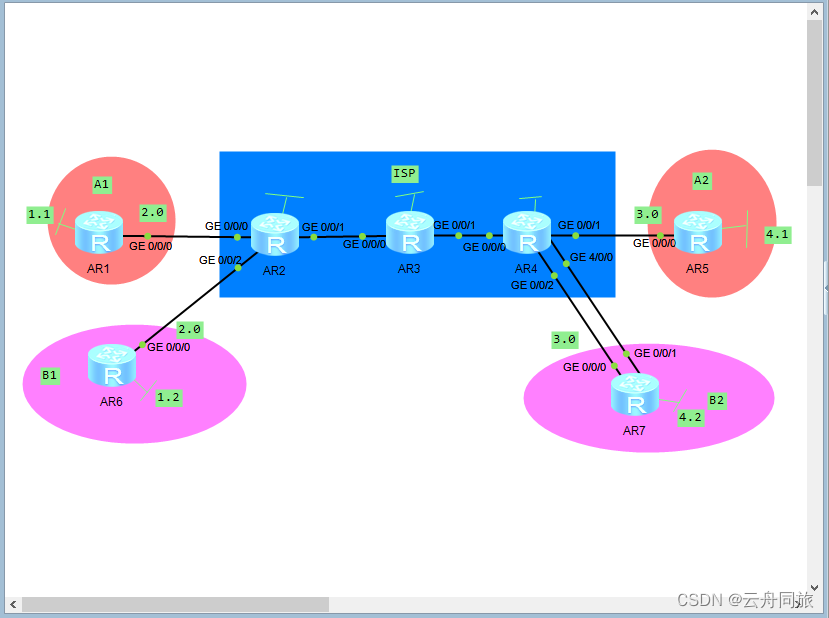
R2ospf 1 router-id 2.2.2.2area 0network 23.1.1.0 0.0.0.255network 2.2.2.0 0.0.0.255R3ospf 1 router-id 3.3.3.3area 0network 23.1.1.0 0.0.0.255network 34.1.1.0 0.0.0.255network 3.3.3.0 0.0.0.255R4ospf 1 router-id 4.4.4.4area 0network 34.1.1.0 0.0.0.255network 4.4.4.0 0.0.0.255
检查R4路由表
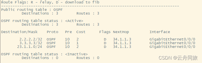
在R2上检测连通性
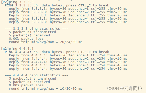
6、MPLS配置
R2mpls lsr-id 2.2.2.2mplsmpls ldpqinterface GigabitEthernet 0/0/1mplsmpls ldpR3mpls lsr-id 3.3.3.3mplsmpls ldpqinterface GigabitEthernet 0/0/0mplsmpls ldpinterface GigabitEthernet 0/0/1mplsmpls ldpR4mpls lsr-id 4.4.4.4mplsmpls ldpqinterface GigabitEthernet 0/0/0mplsmpls ldp
7、MPLS VPN配置
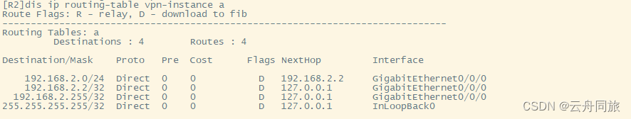
R2ip vpn-instance a route-distinguisher 1:1 vpn-target 1:1 interface GigabitEthernet 0/0/0 ip binding vpn-instance a ip address 192.168.2.2 24 ip vpn-instance broute-distinguisher 2:2vpn-target 2:2interface GigabitEthernet 0/0/2ip binding vpn-instance bip address 192.168.2.2 24
R4ip vpn-instance aroute-distinguisher 1:1vpn-target 1:1interface GigabitEthernet 0/0/1ip binding vpn-instance aip address 192.168.3.2 24ip vpn-instance broute-distinguisher 2:2vpn-target 2:2interface GigabitEthernet 0/0/2ip binding vpn-instance bip address 192.168.3.2 24
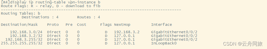
检查私有路由表和测试联通

8、实现公司互通
R1ospf 2area 0network 192.168.1.0 0.0.0.255network 192.168.2.0 0.0.0.255R2ospf 2 vpn-instance aarea 0network 192.168.2.0 0.0.0.255R6ospf 3area 0network 192.168.1.0 0.0.0.255network 192.168.2.0 0.0.0.255R2ospf 3 vpn-instance barea 0network 192.168.2.0 0.0.0.255
R5ospf 2area 0network 192.168.3.0 0.0.0.255network 192.168.4.0 0.0.0.255R4ospf 2 vpn-instance aarea 0network 192.168.3.0 0.0.0.255R7ospf 3area 0network 192.168.3.0 0.0.0.255network 192.168.4.0 0.0.0.255R4ospf 3 vpn-instance barea 0network 192.168.3.0 0.0.0.255
BGP配置
R2bgp 1peer 4.4.4.4 as-number 1peer 4.4.4.4 connect-interface lo0ipv4-family vpnv4peer 4.4.4.4 enableR4bgp 1peer 2.2.2.2 as-number 1peer 2.2.2.2 connect-interface lo0ipv4-family vpnv4peer 2.2.2.2 enable
双向重发布
R2bgp 1ipv4-family vpn-instance aimport-route ospf 2ipv4-family vpn-instance bimport-route ospf 3qospf 2import-route bgpospf 3import-route bgpR4bgp 1ipv4-family vpn-instance aimport-route ospf 2ipv4-family vpn-instance bimport-route ospf 3qospf 2import-route bgpospf 3import-route bgp
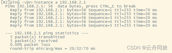
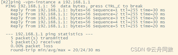
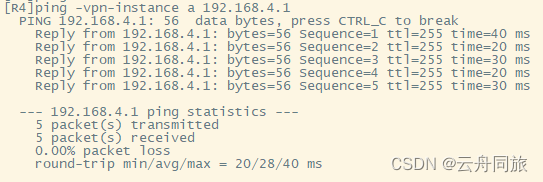
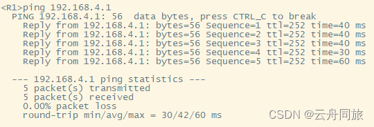
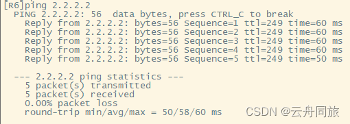
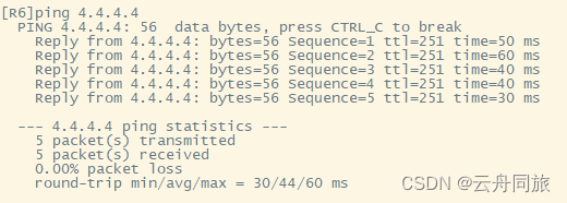
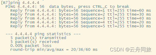
公司A1 ping 公司A2
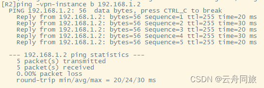
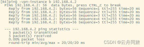
公司B1 ping 公司B2
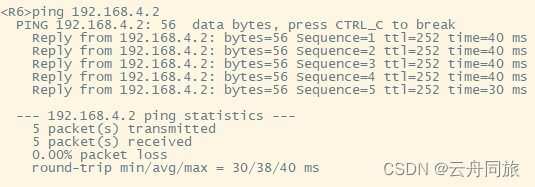
MPLS VPN完成 私网环境(A1与A2 B1与B2)互通
解决R7(公司B2)上网问题 (R4-R7的g4/0/0-g0/0/1属于上网链路)
R4inter g4/0/0ip ad 100.1.1.1 24R7inter g0/0/1ip ad 100.1.1.2 24acl 2000rule permit source anyqinter g0/0/1nat outbound 2000q
下放缺省
R7ospf 3default-route-advertise alwaysqip route-static 0.0.0.0 0 100.1.1.1R4bgp 1network 100.1.1.0 24R3ip route-static 0.0.0.0 0 34.1.1.4R6ip route-static 0.0.0.0 0 192.168.2.2R4bgp 1ipv4-family vpn-instance bdefault-route imported
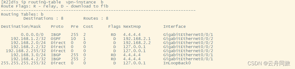
检查R2私有路由表
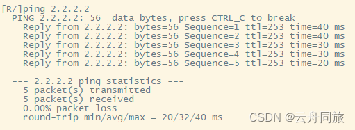
R6、R7上网测试
实验完成
本文来自互联网用户投稿,文章观点仅代表作者本人,不代表本站立场,不承担相关法律责任。如若转载,请注明出处。 如若内容造成侵权/违法违规/事实不符,请点击【内容举报】进行投诉反馈!