链路聚合综合配置示例(路由器和路由器链路聚合---路由器和交换机链路聚合---交换机和交换机链路聚合)
静态LACP链路聚合模式和手动负载均衡链路聚合模式的主要区别:在LACP模式中,一些链路充当备份链路;在手动负载均衡模式中,所有的成员口都处于转发状态。
一、示例展示的要点:
1. 路由器和路由器链路聚合;
2. 路由器和交换机链路聚合;
3. 交换机和交换机链路聚合;
4. 手动负载分担模式;
5. 静态LACP模式(配置设备优先级用于选出主设备,配置端口优先级用于指定备份链路)。
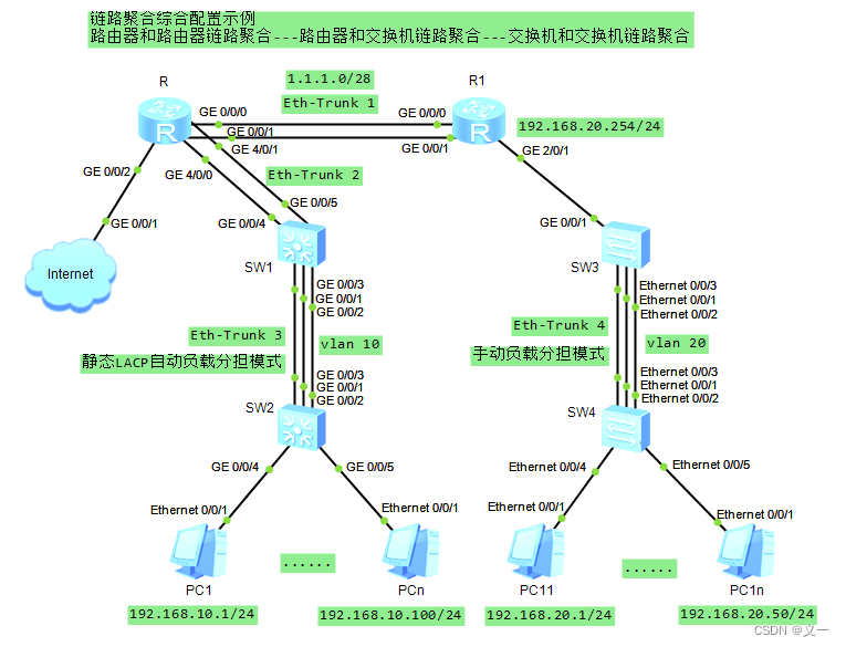
二、示例场景
为实现提高网络带宽和链路备份。
三、示例拓扑图
四、代码段
system-view
sysname R
ip route-static 192.168.20.0 24 1.1.1.2
interface Eth-Trunk 2
undo portswitch
mode lacp-static
trunkport GigabitEthernet 4/0/0 4/0/1
ip address 192.168.10.254 24
interface Eth-Trunk 1
undo portswitch
mode lacp-static
trunkport GigabitEthernet 0/0/0 0/0/1
ip address 1.1.1.1 28system-view
sysname R1
ip route-static 192.168.10.0 24 1.1.1.1
interface Eth-Trunk 1
undo portswitch
mode lacp-static
trunkport GigabitEthernet 0/0/0 0/0/1
ip address 1.1.1.2 28
interface GigabitEthernet 2/0/1
ip address 192.168.20.254 24system-view
sysname SW1
lacp priority 100
vlan 10
interface Eth-Trunk 3
mode lacp-static
port link-type trunk
port trunk allow-pass vlan 10
trunkport GigabitEthernet 0/0/1 to 0/0/3
max active-linknumber 2
interface GigabitEthernet 0/0/1
lacp priority 100
interface GigabitEthernet 0/0/2
lacp priority 100
interface Eth-Trunk 2
mode lacp-static
port link-type access
port default vlan 10
trunkport GigabitEthernet 0/0/4 0/0/5system-view
sysname SW2
vlan 10
interface Eth-Trunk 3
mode lacp-static
port link-type trunk
port trunk allow-pass vlan 10
trunkport GigabitEthernet 0/0/1 to 0/0/3
interface GigabitEthernet 0/0/4
port hybrid untagged vlan 10
port hybrid pvid vlan 10
interface GigabitEthernet 0/0/5
port link-type access
port default vlan 10system-view
sysname SW3
vlan 20
interface Eth-Trunk 4
mode manual load-balance
port link-type trunk
port trunk allow-pass vlan 20
interface Ethernet0/0/1
eth-trunk 4
interface Ethernet0/0/2
eth-trunk 4
interface Ethernet0/0/3
eth-trunk 4
interface GigabitEthernet 0/0/1
port link-type access
port default vlan 20system-view
sysname SW4
vlan 20
interface Eth-Trunk 4
mode manual load-balance
port link-type trunk
port trunk allow-pass vlan 20
trunkport Ethernet 0/0/1 to 0/0/3
interface Ethernet 0/0/4
port link-type access
port default vlan 20
interface Ethernet 0/0/5
port hybrid untagged vlan 20
port hybrid pvid vlan 20
五、代码解释
[Huawei]sysname R
[R]ip route-static 192.168.20.0 24 1.1.1.2 //配置静态路由
[R]interface Eth-Trunk 2 //创建聚合链路端口2
[R-Eth-Trunk2]undo portswitch //将二层网络端口转换成三次网络端口
[R-Eth-Trunk2]mode lacp-static //设置聚合链路2为静态LACP模式
[R-Eth-Trunk2]trunkport GigabitEthernet 4/0/0 4/0/1 //将物理端口GE 4/0/0和GE 4/0/1添加到聚合链路2的端口中
[R-Eth-Trunk2]ip address 192.168.10.254 24
[R-Eth-Trunk2]interface Eth-Trunk 1
[R-Eth-Trunk1]undo portswitch
[R-Eth-Trunk1]mode lacp-static
[R-Eth-Trunk1]trunkport GigabitEthernet 0/0/0 0/0/1
[R-Eth-Trunk1]ip address 1.1.1.1 28
注意:端口加入Eth-Trunk口时,二层Eth-Trunk口的成员口必须是二层端口,三层Eth-Trunk口的成员口必须是三层端口。
[Huawei]sysname R1
[R1]ip route-static 192.168.10.0 24 1.1.1.1 //配置静态路由
[R1]interface Eth-Trunk 1 //创建聚合链路端口1
[R1-Eth-Trunk1]undo portswitch //将二层网络端口转换成三次网络端口
[R1-Eth-Trunk1]mode lacp-static //设置聚合链路1为静态LACP模式
[R1-Eth-Trunk1]trunkport GigabitEthernet 0/0/0 0/0/1 //将物理端口GE 0/0/0和GE 0/0/1添加到聚合链路1的端口中
[R1-Eth-Trunk1]ip address 1.1.1.2 28
[Huawei]sysname SW1
[SW1]lacp priority 100 //设置SW1交换机lacp优先级为100
[SW1]vlan 10
[SW1-vlan10]interface Eth-Trunk 3 //创建聚合链路端口3
[SW1-Eth-Trunk3]mode lacp-static //设置聚合链路1为静态LACP模式
[SW1-Eth-Trunk3]port link-type trunk //设置聚合链路端口3的vlan端口链路类型为trunk
[SW1-Eth-Trunk3]port trunk allow-pass vlan 10 //设置聚合链路端口3允许vlan 10数据通过
[SW1-Eth-Trunk3]trunkport GigabitEthernet 0/0/1 to 0/0/3 //将物理端口GE 0/0/1、GE 0/0/2和GE 0/0/1添加到聚合链路1的端口中
[SW1-Eth-Trunk3]max active-linknumber 2 //设置活动链路上限数为2个
[SW1-Eth-Trunk3]interface GigabitEthernet 0/0/1
[SW1-GigabitEthernet0/0/1]lacp priority 100 //设置SW1交换机GE0/0/1端口lacp优先级为100
[SW1-GigabitEthernet0/0/1]interface GigabitEthernet 0/0/2
[SW1-GigabitEthernet0/0/2]lacp priority 100 //设置SW1交换机GE0/0/2端口lacp优先级为100
[SW1-GigabitEthernet0/0/2]interface Eth-Trunk 2 //创建聚合链路端口2
[SW1-Eth-Trunk2]mode lacp-static //设置聚合链路1为静态LACP模式
[SW1-Eth-Trunk2]port link-type access //设置聚合链路端口2的vlan端口链路类型为access
[SW1-Eth-Trunk2]port default vlan 10 //设置聚合链路端口2允许vlan 10数据通过
[SW1-Eth-Trunk2]trunkport GigabitEthernet 0/0/4 0/0/5 //将物理端口GE 0/0/4和GE 0/0/5添加到聚合链路2的端口中
[Huawei]sysname SW2
[SW2]vlan 10
[SW2-vlan10]interface Eth-Trunk 3 //创建聚合链路端口3
[SW2-Eth-Trunk3]mode lacp-static //设置聚合链路1为静态LACP模式
[SW2-Eth-Trunk3]port link-type trunk //设置聚合链路端口3的vlan端口链路类型为trunk
[SW2-Eth-Trunk3]port trunk allow-pass vlan 10 //设置聚合链路端口3允许vlan 10数据通过
[SW2-Eth-Trunk3]trunkport GigabitEthernet 0/0/1 to 0/0/3 //将物理端口GE 0/0/1、GE 0/0/2和GE 0/0/1添加到聚合链路1的端口中
[SW2-Eth-Trunk3]interface GigabitEthernet 0/0/4
[SW2-GigabitEthernet0/0/4]port hybrid untagged vlan 10 //交换机在该端口转发VLAN10的帧时,剥离掉相应的VLAN Tag 10,以Untagged的方式发送出去。
[SW2-GigabitEthernet0/0/4]port hybrid pvid vlan 10 //设置Hybrid类型端口的VLAN ID,即该端口上接收到未带VLAN Tag的帧时,加上VLAN Tag 10再转发。
[SW2-GigabitEthernet0/0/4]interface GigabitEthernet 0/0/5
[SW2-GigabitEthernet0/0/5]port link-type access //设置GE0/0/5的vlan端口链路类型为access
[SW2-GigabitEthernet0/0/5]port default vlan 10 //设置GE0/0/5允许vlan 10数据通过
[Huawei]sysname SW3
[SW3]vlan 20
[SW3-vlan20]interface Eth-Trunk 4 //创建聚合链路端口4
[SW3-Eth-Trunk4]mode manual load-balance //设置聚合链路4为手动负载分担模式
[SW3-Eth-Trunk4]port link-type trunk //设置聚合链路端口4的vlan端口链路类型为trunk
[SW3-Eth-Trunk4]port trunk allow-pass vlan 20 //设置聚合链路端口4允许vlan 20数据通过
[SW3-Eth-Trunk4]interface Ethernet0/0/1
[SW3-Ethernet0/0/1]eth-trunk 4 //将物理端口E 0/0/1添加到聚合链路4的端口中
[SW3-Ethernet0/0/1]interface Ethernet0/0/2
[SW3-Ethernet0/0/2]eth-trunk 4 //将物理端口E 0/0/2添加到聚合链路4的端口中
[SW3-Ethernet0/0/2]interface Ethernet0/0/3
[SW3-Ethernet0/0/3]eth-trunk 4 //将物理端口E 0/0/3添加到聚合链路4的端口中
[SW3-Ethernet0/0/3]interface GigabitEthernet 0/0/1
[SW3-GigabitEthernet0/0/1]port link-type access //设置GE0/0/1的vlan端口链路类型为access
[SW3-GigabitEthernet0/0/1]port default vlan 20 //设置GE0/0/1允许vlan 20数据通过
[Huawei]sysname SW4
[SW4]vlan 20
[SW4-vlan20]interface Eth-Trunk 4
[SW4-Eth-Trunk4]mode manual load-balance
[SW4-Eth-Trunk4]port link-type trunk
[SW4-Eth-Trunk4]port trunk allow-pass vlan 20
[SW4-Eth-Trunk4]trunkport Ethernet 0/0/1 to 0/0/3
[SW4-Eth-Trunk4]interface Ethernet 0/0/4
[SW4-Ethernet0/0/4]port link-type access
[SW4-Ethernet0/0/4]port default vlan 20
[SW4-Ethernet0/0/4]interface Ethernet 0/0/5
[SW4-Ethernet0/0/5]port hybrid untagged vlan 20
[SW4-Ethernet0/0/5]port hybrid pvid vlan 20
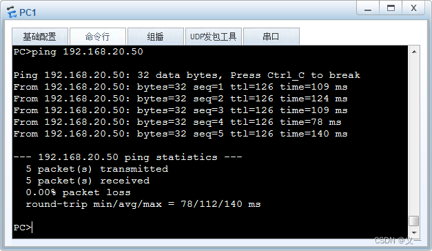
六、测试验证
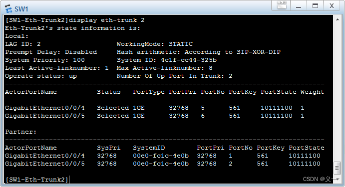
使用display eth-trunk 命令查看Eth-Trunk 1接口状态,测试聚合链路备用端口切换启用。
如果将SW1的GE 0/0/2端口down掉: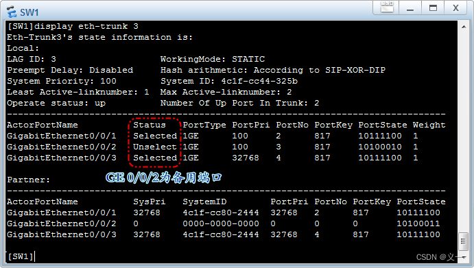
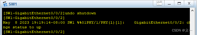
开启SW1的GE 0/0/2端口:
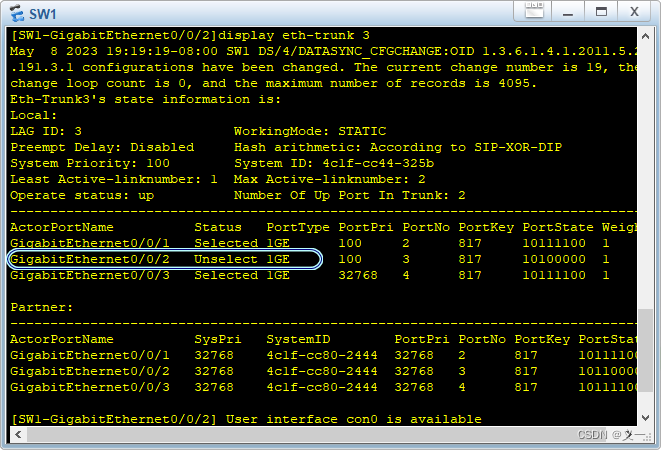
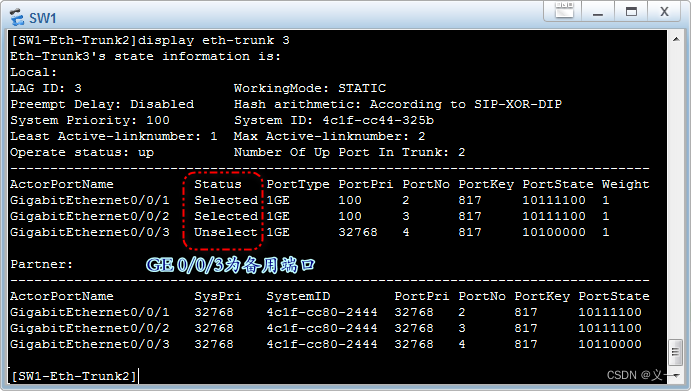
SW1的GE 0/0/2端口从故障状态恢复正常后,没有自动变成活动状态。
使用display interface eth-trunk 命令查看Eth-Trunk 1接口信息
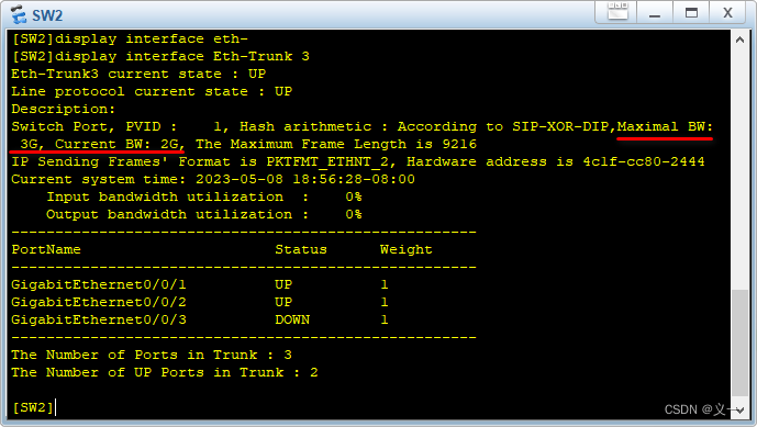
Eth-Trunk 3为2G,是两个GE端口带宽之和,GE0/0/3接口为Eth-Trunk 3的备用接口。
参考链接:https://www.cnblogs.com/gucun-blog/p/16369443.html
http://t.csdn.cn/U9rZy
本文来自互联网用户投稿,文章观点仅代表作者本人,不代表本站立场,不承担相关法律责任。如若转载,请注明出处。 如若内容造成侵权/违法违规/事实不符,请点击【内容举报】进行投诉反馈!