重型汽车制动器设计
重型自卸汽车设计(制动系设计)
本次我们设计的课题是64T重型自卸汽车。我的任务是负责汽车的制动系的设计。该制动系统的主要用途是使行驶中的汽车减速甚至停车,使下坡的汽车速度保持平稳,以及使已停驶的汽车保持不动。
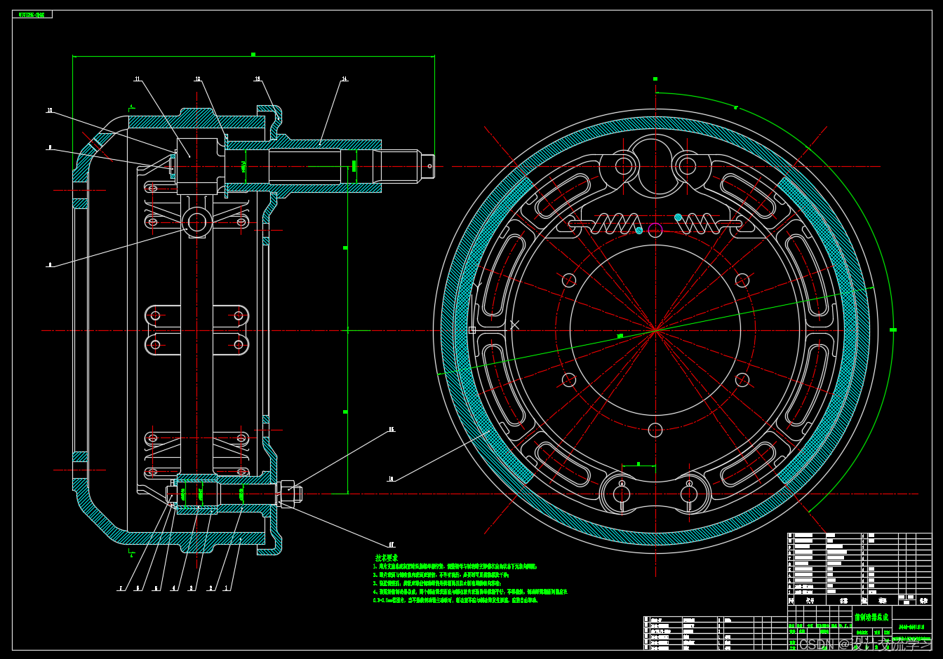
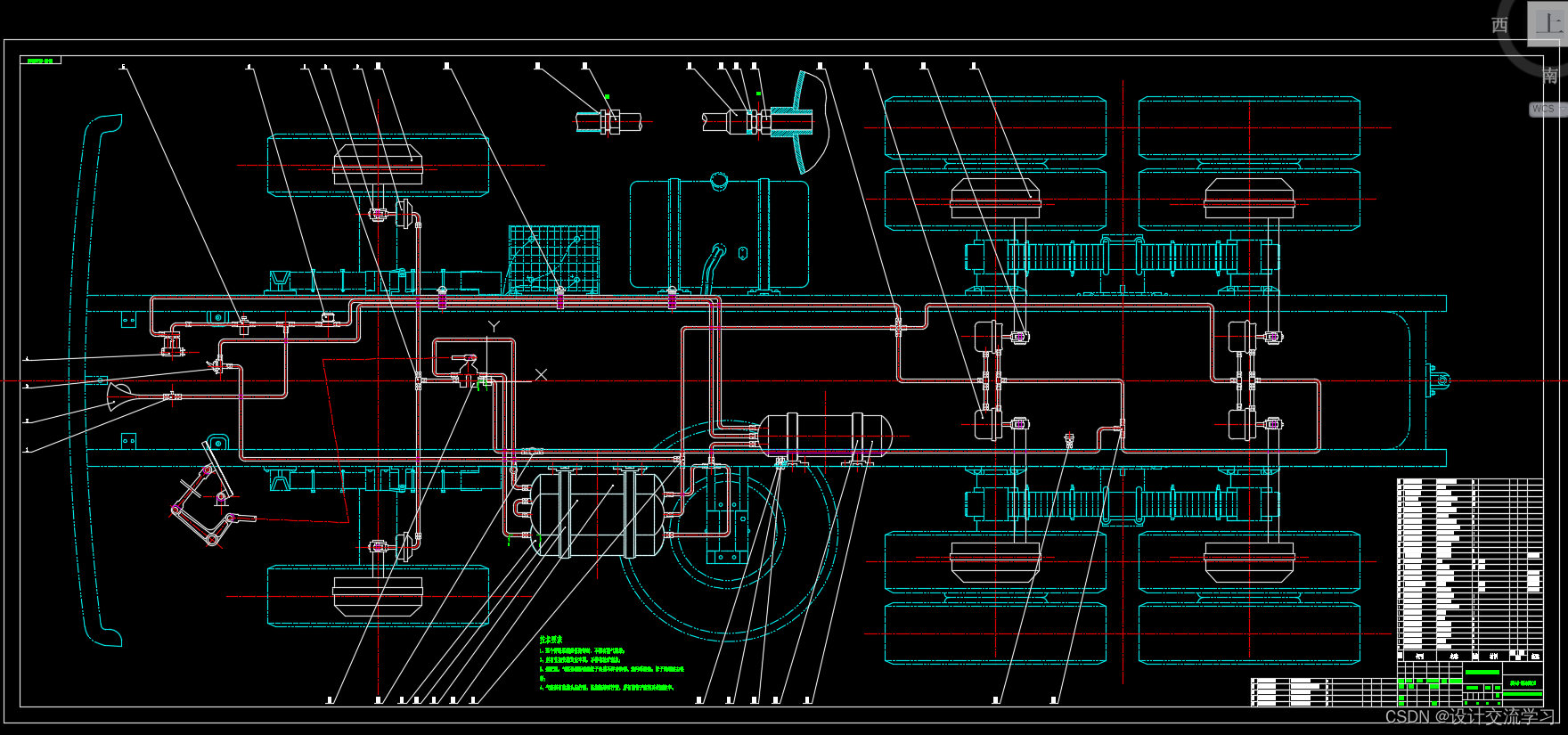
本次设计的制动系主要设计方案包含行车制动系统与驻车制动系统两套系统。结构形式方面选用凸轮驱动领从蹄式制动器。采用双回路气力驱动制动系统。前制动气室采用膜片式制动气室,后制动气室采用复合式制动气室。行车制动系统作用在前、后轮上。驻车制动系统为放气制动式,作用于中、后轮上,用手制动阀操纵。当行车制动失效时,驻车制动可做紧急制动用。
本次制动系的设计在工作过程中安全可靠,在初速为30km/h时制动距离小于10m,驻车坡度大于35%,制动轻便等都满足了设计要求;而且在任何速度下制动时,汽车都不丧失操纵性和方向稳定性。当制动驱动装置的任何元件发生故障并使其基本功能遭到破坏时,汽车制动系都通过传感器传递信号对驾驶员给于音响或光信号等报警提示。从而提高行车安全性。
关键词:制动系,制动蹄,气力驱动,凸轮
DESIGN OF HEAVY-DUTY DUMP TRUCK
(DENSIGN OF BRAKING SYSTEM)
ABSTRACT
The design of our 64T is the subject of heavy dump truck. My task is responsible for vehicle braking system design. The brake system’s main purpose is to make teavelling in the car slow down or even stopping, the downhill speed of the car remained stable, and to stopthe car has to keep moving.
The design of the braking system design options include road vehicl braking systems and brake system in the two systems. Structure in the form of optional cam drive leading trailing. Dual-circuit efforts to drive braking system. Brake chamber before a patch-brake chamber, after the brake chamber used composite brake chamber. Road brake sysrem of the former, on the rear. Braking system for traffic-gas-brake, in effect, the rear wheels, manipulated by hand Zhidong Fa. When the lane brake failure, the car brakes with emergency brake to do.
The braking system design in the course of their work secure in the muzzle velocity of 30km/h when the braking distance of less than 10m, the slope is greater than 35% of car, brake light and so meet the design requirements and in any speed under the brake, do not lose control of the vehicle and direction of stability. When the brake drive any component failure and the destruction of its basic functions,through the vehicle braking system sensors send signals to the drivers to sound or light signals in the police and other tips. So as to enhance traffic safety.
Keywords:Braking system, Brake shoes, Pneumatic-driven,Cam
目 录
第一章 绪论
§1.1本课题的目的和意义
§1.2汽车制动系在国内外的研究状况及发展趋势
§1.3鼓式制动器技术研究进展和现状
§1.4研究重点
第二章 汽车总体参数的选择及计算
§2.1汽车形式的确定
2.1.1 轴数
2.1.2驱动形式
2.1.3布置形式
§2.2汽车质量参数的确定
2.2.1质量系数
2.2.2汽车总质量
2.2.3载荷分配
§2.3汽车主要数据的确定
2.3.1质心高度
2.3.2轴距
第三章 制动器的结构型式及要求
§3.1鼓式制动器的结构形式
3.1.1领从蹄式制动器
3.1.2单向双领蹄式制动器
3.1.3双向双领蹄式制动器
3.1.4双从蹄式制动器
3.1.5单向增力式制动器
3.1.6双向增力式制动器
§3.2鼓式制动器方案的确定
第四章 理想制动力及其分配
§4.1 制动力与制动力分配系数
§4.2 同步附着系数
§4.3制动器最大制动力矩
第五章 制动器的设计计算
§5.1 鼓式制动器的结构参数
5.1.1 制动鼓内径D
5.1.2 摩擦衬片宽度b和包角
5.1.3 摩擦衬片起始角
5.1.4 制动器中心到张开力作用线的距离e
5.1.5 制动蹄支承点位置坐标a和c
5.1.6 摩擦片摩擦系数
§5.2制动蹄片上的制动力矩
§5.3 行车制动效能计算
§5.4 驻车制动计算
§5.5 摩擦衬片的磨损特性计算
第六章 制动器的结构及主要零部件设计
§6.1制动蹄
§6.2制动鼓
§6.3摩擦衬片
§6.4摩擦材料
§6.5蹄与鼓之间的间隙自动调整装置
§6.6制动支承装置
§6.7张开机构
§6.8制动蹄回位弹簧
第七章 制动驱动机构的结构形式选择与设计计算
§7.1 制动驱动机构的结构形式选择
§7.2 气压驱动机构的设计计算
第八章 结论
参考文献
致谢
外文资料
外文资料译文
…………

本文来自互联网用户投稿,文章观点仅代表作者本人,不代表本站立场,不承担相关法律责任。如若转载,请注明出处。 如若内容造成侵权/违法违规/事实不符,请点击【内容举报】进行投诉反馈!