【STM32】ESP8266 WiFi模块实时上报温湿度及控制LED灯项目笔记
ESP8266 WiFi模块实时上报温湿度及控制LED灯项目笔记
- 一、ESP8266模块
- 1.模块介绍
- 2.AT指令介绍
- 2.硬件连接
- 二、串口转发及调试
- 1.串口转发流程
- 2.串口转发程序实现
- STM32CubeMX配置
- 修改usart.h/.c文件
- 修改main.c文件
- 3.运行测试
- 三、AT指令学习
- 1.WiFi初始化命令
- 2.无线连接命令
- 3.数据收发命令
- 四、WiFi模块实时上报温湿度与远程控制LED灯实现
- 1.esp8266.h/.c
- 2.main.c
- 3.运行测试
- 总结
一、ESP8266模块
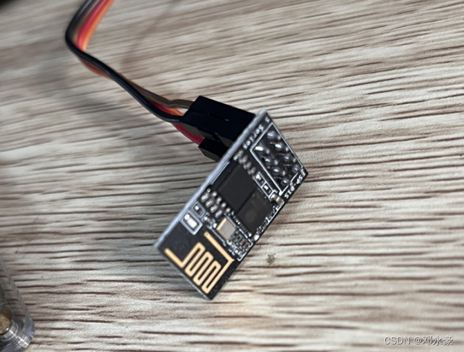
1.模块介绍
本项目无线通讯模块使用的是WiFi模块ESP8266,乐鑫公司推出的高性能、低功耗串口WiFi模块ESP8266应该是使用最广泛的一种WIFI模块之一了,它自身带有高性能的MCU(Microcontroller Unit),因此它既可以通过串口连接为外部MCU提供 WiFi通信功能,也就是我们本项目所用到的功能;当然它也可以让用户直接在模块内置的MCU上基于RTOS SDK进行软件编程,开发出具有低功耗、低成本的WiFi连接产品,如市面上大部分WiFi智能插座就用了ESP8266模块和它的这一功能。
ESP8266内置一个Tensilica(泰思立达)Xtensa架构的32位处理器L106,具有5级流水线(ARM CortexM3是3级流水线),最大时钟速度为160MHz,可以使用高达16MB的外部SPI Flash。该模块采用串口与MCU(或其他串口设备)通信,内置 TCP/IP协议栈,能够实现串口与 WiFi之间的转换。通过该模块,传统的串口设备只需要简单的串口配置,即可通过WiFi传输自己的数据。
WiFi具有两种功能模式:一种叫AP(Access Point)模式,一种叫Station模式。AP就是我们平时所说的热点,如无线路由器,开了热点的手机等,这些AP设备可以允许其他设备(如手机,PC等)输入热点名(SSID)和密码(也可不设置密码)后连接上网;Station模式则是前面说的连接AP的设备(如手机,PC等)。
ESP8266除支持上述两种模式以外,还可以支持第三种模式:AP+Station,即:将AP和Station的功能合二为一,它主要是实现无线桥接的功能,该模式应用的场景不多。
STM32单片机在与ESP8266进行串口通信时采用AT命令进行通信,这样想要做ESP8266 WiFi模块的程序开发的话,那我们首先得学习并熟练掌握ESP8266 WiFi模块的AT指令。
2.AT指令介绍
AT指令是以AT作为开头,\r\n字符结束的字符串,每个指令执行成功与否都有相应的返回。其他的一些非预期的信息(如有人拨号进来、线路无信号等),模块将有对应的一些信息提示,接收端可做相应的处理。
不同模块的AT命令可能不一样的,这要对着模块的AT指令手册来查看。
AT命令可分为四类:
| 类型 | 指令格式 | 描述 |
|---|---|---|
| 执行指令 | AT+ | 该命令用于执行受模块内部程序控制的变参数不可变的功能。 |
| 测试指令 | AT+=? | 该命令用于该命令用于查询设置指令的参数以及取值范围。 |
| 查询指令 | AT+? | 该命令用于返回参数的当前值。 |
| 设置指令 | AT+=<···> | 该命令用于设置用户自定义的参数值。 |
2.硬件连接
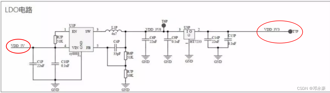
由于我的开发板当中3.3V电源是LDO电路从USB TypeC接口提供的5V降压而来,电流较低,所以连ESP8266模块可能会导致它不能正常工作,所以这里我连了5V做VCC,而我所用的ESP8266能够正常工作,具体所用的时候可以视情况而定。
提示:USB3.0的接口电流较高,如果必要用5V,最好不用USB3.0
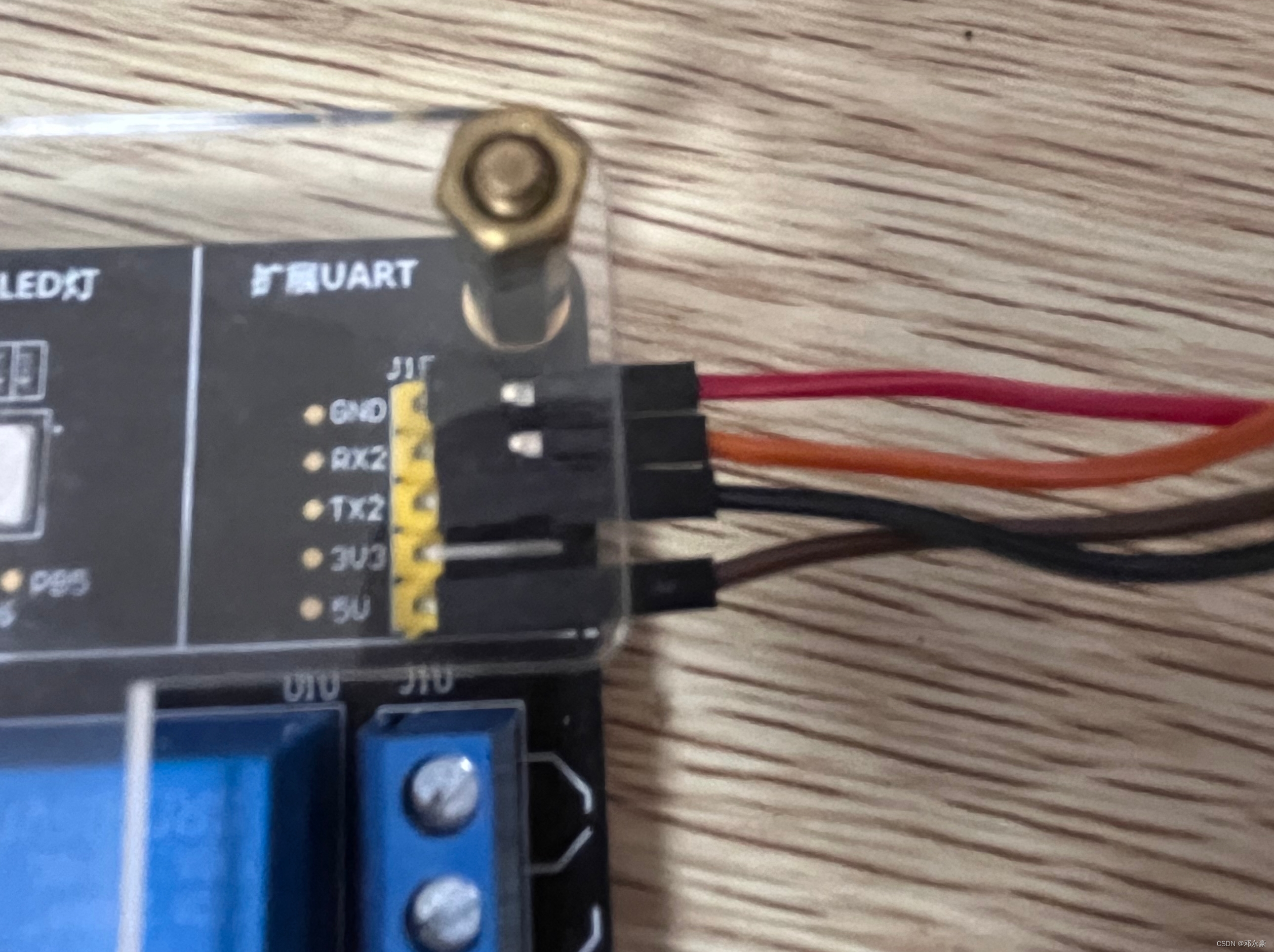
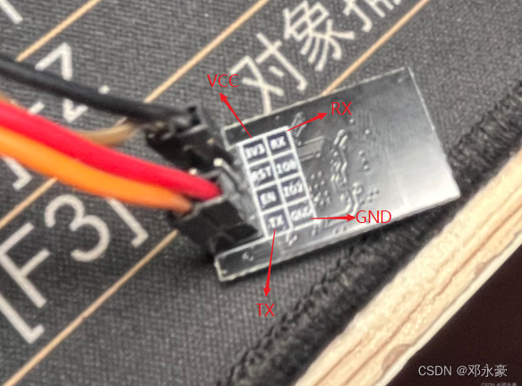
ESP8266模块提供TTL串口通信接口,而我所使用的开发板上的扩展UART2串口也是TTL电平,所以直接连接如下:
二、串口转发及调试
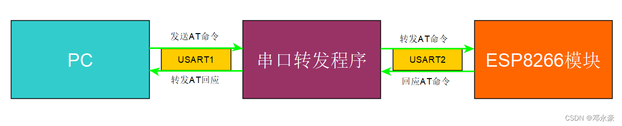
1.串口转发流程
开发板的USART2串口连接了ESP8266模块,当然我们要通过PC来对它进行调试,所以我们需要STM32写一个单片机上写一个串口接收转发的程序如下图:
2.串口转发程序实现
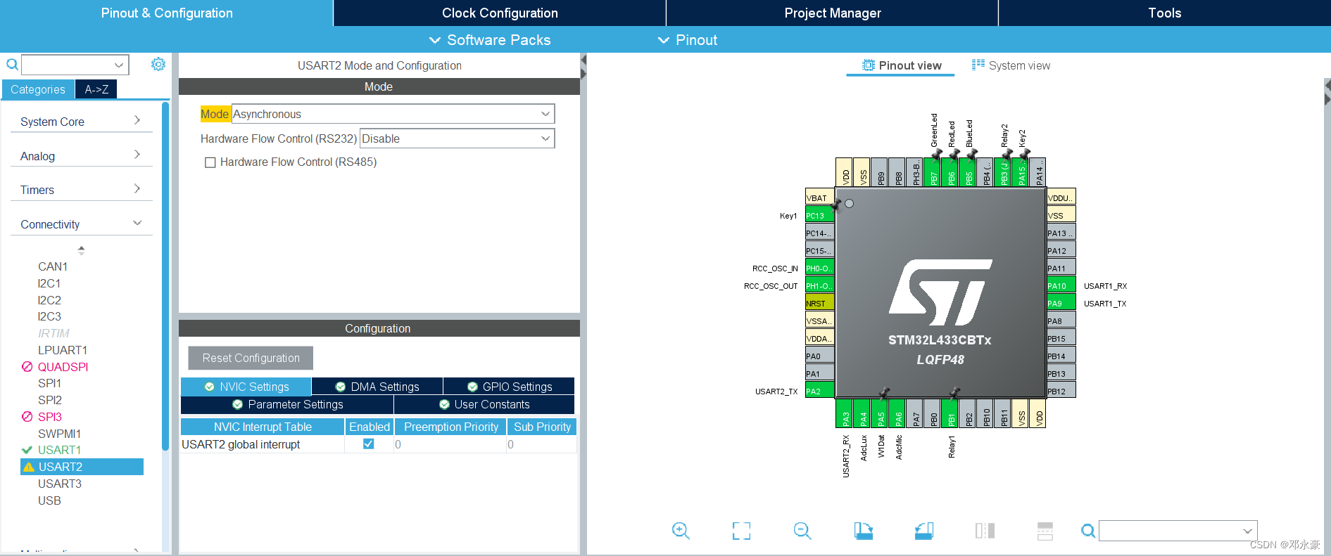
STM32CubeMX配置
修改usart.h/.c文件
对usart.h文件做如下修改:
... ...
/* USER CODE BEGIN Private defines */
extern char g_uart1_rxbuf[256];
extern uint8_t g_uart1_bytes;#define clear_uart1_rxbuf() do { memset(g_uart1_rxbuf, 0, sizeof(g_uart1_rxbuf)); \g_uart1_bytes=0; } while(0)//在这里添加uar2接收 buffer相关变量声明,并添加一个宏 clear_uart2_rxbuf()用来清除接收 buffer里的数据
extern char g_uart2_rxbuf[256];
extern uint8_t g_uart2_bytes;#define clear_uart2_rxbuf() do { memset(g_uart2_rxbuf, 0, sizeof(g_uart2_rxbuf)); \g_uart2_bytes=0; } while(0)//添加串口接收转发函数的声明
extern void uart_forward(void);/* USER CODE END Private defines */
... ...
对usart.c文件做如下修改:
... ...
/* USER CODE BEGIN 0 */
static	uint8_t			s_uart1_rxch;
char					g_uart1_rxbuf[256];
uint8_t					g_uart1_bytes;static	uint8_t			s_uart2_rxch;
char					g_uart2_rxbuf[256];
uint8_t					g_uart2_bytes;
/* USER CODE END 0 */
... ...void MX_USART2_UART_Init(void)
{
... .../* USER CODE BEGIN USART2_Init 2 */HAL_UART_Receive_IT(&huart2 , &s_uart2_rxch, 1);//HAL_UART_Receive_IT中断服务处理程序/* USER CODE END USART2_Init 2 */}
... .../* USER CODE BEGIN 1 */
void HAL_UART_RxCpltCallback(UART_HandleTypeDef *huart)
{if (huart->Instance == USART1){if( g_uart1_bytes< sizeof(g_uart1_rxbuf) ){g_uart1_rxbuf[g_uart1_bytes++] = s_uart1_rxch;}HAL_UART_Receive_IT(&huart1 , &s_uart1_rxch, 1);}if (huart->Instance == USART2){if( g_uart2_bytes< sizeof(g_uart2_rxbuf) ){g_uart2_rxbuf[g_uart2_bytes++] = s_uart2_rxch;}HAL_UART_Receive_IT(&huart2 , &s_uart2_rxch, 1);}
}//添加usart1和usart2的收发转发功能函数,main()函数中调用
void uart_forward(void)
{if(strstr(g_uart1_rxbuf, "\r\n")){HAL_UART_Transmit(&huart2, (uint8_t *)g_uart1_rxbuf, g_uart1_bytes,0xFF);clear_uart1_rxbuf();}if(g_uart2_bytes > 0){HAL_Delay(100);/*Wait AT command reply receive over*/HAL_UART_Transmit(&huart1, (uint8_t *)g_uart2_rxbuf, g_uart2_bytes,0xFF);clear_uart2_rxbuf();}
}
... .../* USER CODE END 1 */... ...
修改main.c文件
如下:
... ...while(1){uart_forward();//后面使用无线通讯时只需要用Socket通信,不在需要此转发程序,如果没有注释掉会报错,并不会执行PC发的JOSN指令
#if 0
... ...
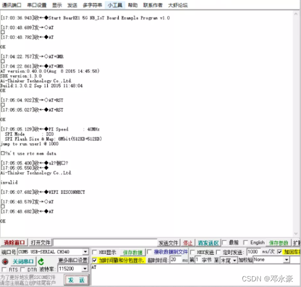
#endif/* USER CODE END WHILE *//* USER CODE BEGIN 3 */}... ...3.运行测试
用串口调试工具进行测试:
三、AT指令学习
每一个使用AT指令通信的模块都有自己详细的AT指令使用说明文档,模块里的软件固件版本不一样,其AT指令可能也不大一样,可以通过你的模块以及版本找到对应的说明文档对照。
对于我所使用的ESP8266 WiFi模块:
1.WiFi初始化命令
| AT命令 | 说明 |
|---|---|
| AT | AT命令用来确认模块是否正常工作以及串口通信是否正常 |
| AT+GMR | 获取WiFi模块的软件固件版本信息 |
| AT+RST | 重启、复位WiFi模块 |
| AT+CWMODE_CUR=1 | 设置ESP8266 WiFi模块工作在Station模式 |
| AT+CWDHCP_CUR=1,1 | 设置使能ESP8266 WiFi模块Station模式的DHCP服务 |
| AT+CIPSTA_CUR | 静态设置ESP8266的IP地址,子网掩码和默认网关 |
2.无线连接命令
| AT命令 | 说明 |
|---|---|
| AT+CWJAP_CUR=“Router_SSID” ,“Password” | 该命令用来连接指定的无线路由器 |
| AT+CIPSTA_CUR? | 该命令用来查看ESP8266当前的IP地址 |
| AT+PING=“192.168.0.1” | 该命令用来测试与目标主机的连通性 |
3.数据收发命令
| AT命令 | 说明 |
|---|---|
| AT+CIPMUX=0 | 该命令用来禁用多个socket连接,一般只连接一个目标服务器。 |
| AT+CIPSTART=“TCP”,“192.168.0.100"”,12345 | 该命令用来连接指定的目标socket 服务器 |
| AT+CIPSEND=5 | 该命令用来发送5个字节的数据,在收到模块回应的‘>’字符后,开始输入要发送的数据内容。 |
| AT+CIPCLOSE | 该命令用来断开Socket连接 |
注意:指令带_CUR后缀则表示只更改当前系统配置,并不写入Flash存储器中,重启复位后失效。而如果需要重启后依然有效则用带_DEF后缀的命令。
四、WiFi模块实时上报温湿度与远程控制LED灯实现
1.esp8266.h/.c
代码如下:
/** esp8266.h** Created on: 2023年2月26日* Author: ASUS*/#ifndef INC_ESP8266_H_
#define INC_ESP8266_H_#include /** esp8266.c** Created on: 2023年2月26日* Author: ASUS*/#include 2.main.c
代码如下:
/* USER CODE BEGIN Header */
/********************************************************************************* @file : main.c* @brief : Main program body******************************************************************************* @attention** © Copyright (c) 2022 STMicroelectronics.* All rights reserved.
** This software component is licensed by ST under BSD 3-Clause license,* the "License"; You may not use this file except in compliance with the* License. You may obtain a copy of the License at:* opensource.org/licenses/BSD-3-Clause********************************************************************************/
/* USER CODE END Header */
/* Includes ------------------------------------------------------------------*/
#include "main.h"
#include "adc.h"
#include "tim.h"
#include "usart.h"
#include "gpio.h"/* Private includes ----------------------------------------------------------*/
/* USER CODE BEGIN Includes */
#include 注意:需要注释掉转发程序,不然无法控制Led灯
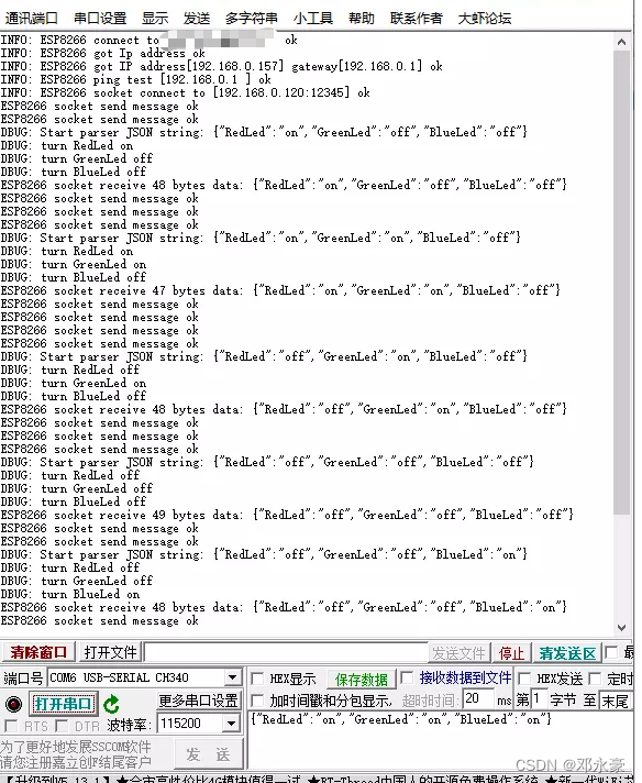
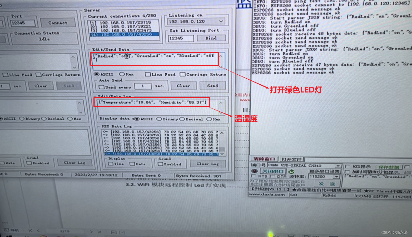
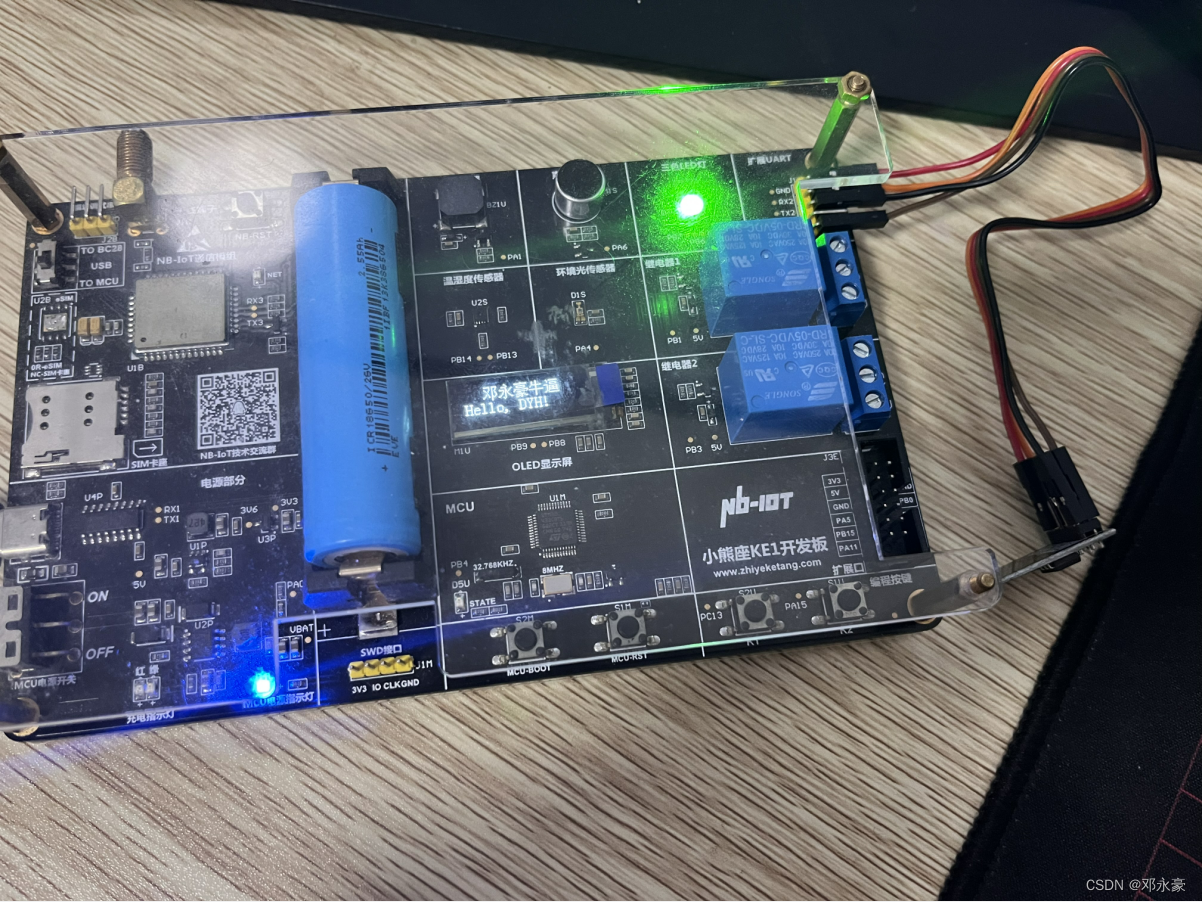
3.运行测试
总结
首先,对于STM32单片机在写博客之前学习了,所以没有,之后可能也会对之前的内容整理为博客,包括Led、DHT11、SHT30、I2C协议、SPI协议及JSON格式远程控制等,所以之前内容并未包括在此篇当中。
本篇为ESP8266 WiFi模块实时上报温湿度及控制LED灯项目笔记,主要介绍和应用了ESP8266 WiFi模块,编写了串口转发程序,学习了AT命令等,最终实现了ESP8266 WiFi模块实时上报温湿度及控制LED灯项目。
别忘了点赞 关注 收藏呀!
本文来自互联网用户投稿,文章观点仅代表作者本人,不代表本站立场,不承担相关法律责任。如若转载,请注明出处。 如若内容造成侵权/违法违规/事实不符,请点击【内容举报】进行投诉反馈!